Closure safety interlock with lockout plate for pressure vessel

a technology of safety interlocking and pressure vessel, which is applied in the direction of locking devices, manufacturing tools, and discharging methods of containers, can solve the problems of preventing the ability to force the bolts out of the holding lugs, and achieve the effects of minimizing the misuse of the primary locking system, minimizing the operator's ability to use a hammer, and good visual indication of the condition of the tank

Inactive Publication Date: 2016-12-01
AMBRIZ STEVEN RICHARD
View PDF42 Cites 0 Cited by
  • Summary
  • Abstract
  • Description
  • Claims
  • Application Information

AI Technical Summary

Benefits of technology

[0019]In the broadest sense, the closure safety interlock system of the present inventions is adapted for a pressure vessel having a closure assembly with a primary locking system. The closure safety interlock defines a secondary locking system for assuring that the primary locking system may be opened only by following a proper sequence, thereby minimizing misuse of the primary locking system. In the preferred embodiment, the closure safety interlock includes a lockout plate and a blocking member movable between an engaged position and a disengaged position for blocking movement of a primary lock when in the engaged position and until a release mechanism in the primary lock has been activated. A mechanism is provided for moving the blocking member from the engaged position to the disengaged position once the release mechanism has been activated. In the preferred embodiment the safety interlock also includes sequencing indicia indicating the sequence which should be followed in activating the release mechanism. A limiter device may be provided for limiting the movement of the blocking member from the engaged position to the disengaged position.
[0020]In its preferred form the closure safety interlock system includes a locking plate and an interlock shield mounted over the swing nuts and closure head components of the closure assembly. The shield may be moved between a locking position and an open position. When in the locking position, it blocks access to the swing bolts, prohibiting the ability to force the bolts out of the holding lugs until all camlock handles have been rotated to the open position. This assures that the closure head will move as intended if the tank is under pressure or will remain properly seated in the hub if the tank is not under pressure, giving a good visual indication of the condition of the tank before opening the closure head.
[0021]In the preferred embodiment of the invention, the closure safety interlock shield includes a plurality of spokes or arms in one-to-one relationship with the swing bolts. The shield is mounted directly on the closure head. The shield is rotatable between a locked position wherein the spokes cover bolts, prohibiting the bolts from swinging out of the holding lugs and an opened position providing unrestricted access to the bolts. A gap exists between each pair of spokes, each gap adapted for accommodating one camlock handle when the handle is in the locked position. This prevents rotation of the shield until all of the camlock handles have been moved to the open position, assuring proper opening sequence of the closure head.
[0022]It is desirable to provide limitation of rotation of the shield to assure proper alignment of the shield spokes with the swing bolt assemblies, particularly when the bolts are not equally spaced around the perimeter of the closure head. It is also desirable to provide a positive indicator for determining when the shield is in the open and the locked positions.
[0023]The closure safety interlock of the present invention prevents the operator from opening the closure head in an incorrect sequence by blocking the operation of the swing bolts until all of the camlock handles are in the open position. This opening sequence is necessary to maintain the “designed in” alerting feature of the closure which indicates the presence of air pressure within the pressure vessel.
[0024]The closure safety interlock also shields the swing bolts and thereby minimizing the operator's ability to use a hammer or other device to aid in moving the swing bolts to the open position when any camlock handle is in the locked position.

Problems solved by technology

When in the locking position, it blocks access to the swing bolts, prohibiting the ability to force the bolts out of the holding lugs until all camlock handles have been rotated to the open position.

Method used


Image

  • Closure safety interlock with lockout plate for pressure vessel
  • Closure safety interlock with lockout plate for pressure vessel
  • Closure safety interlock with lockout plate for pressure vessel

Examples


Embodiment Construction

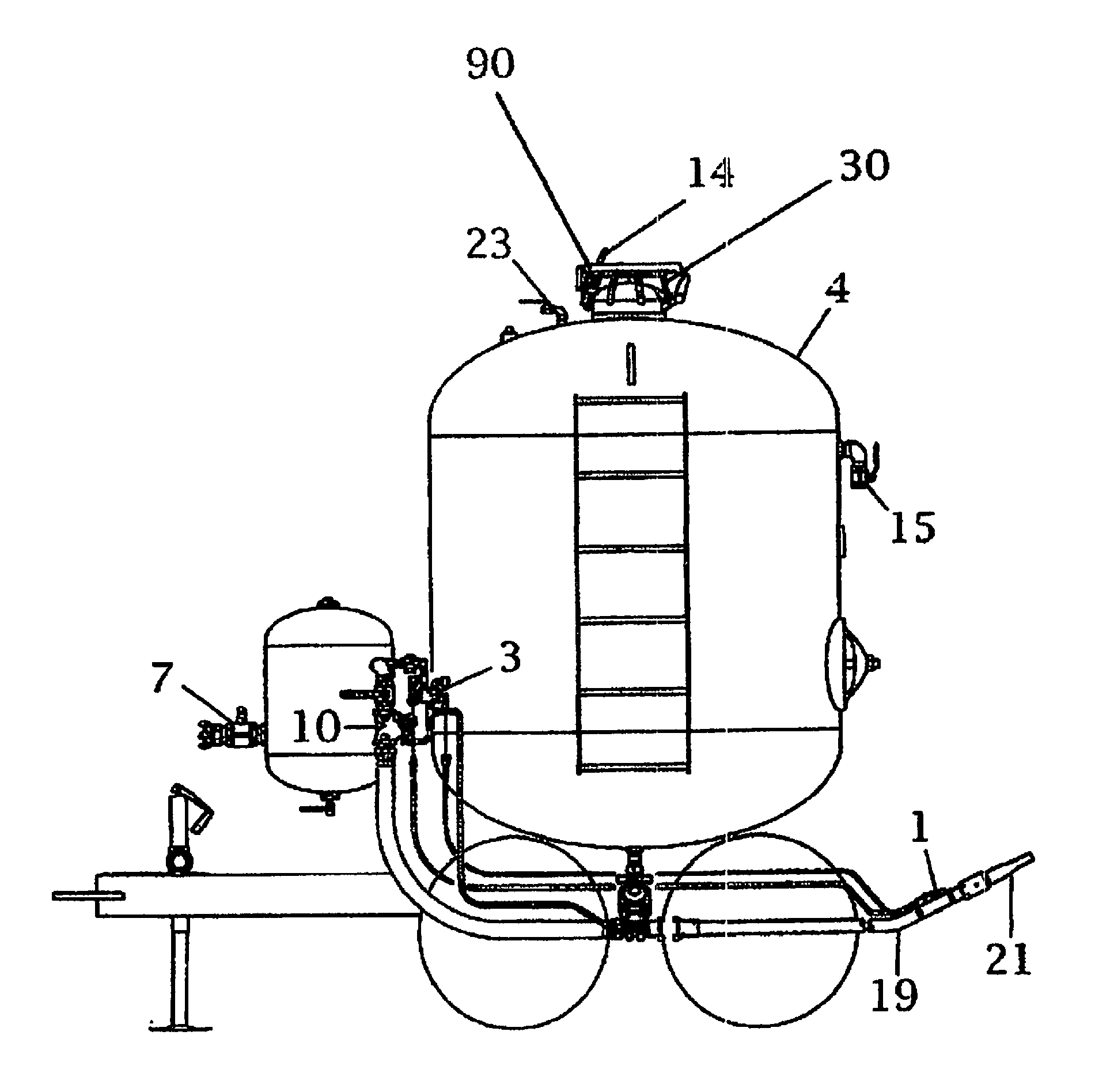
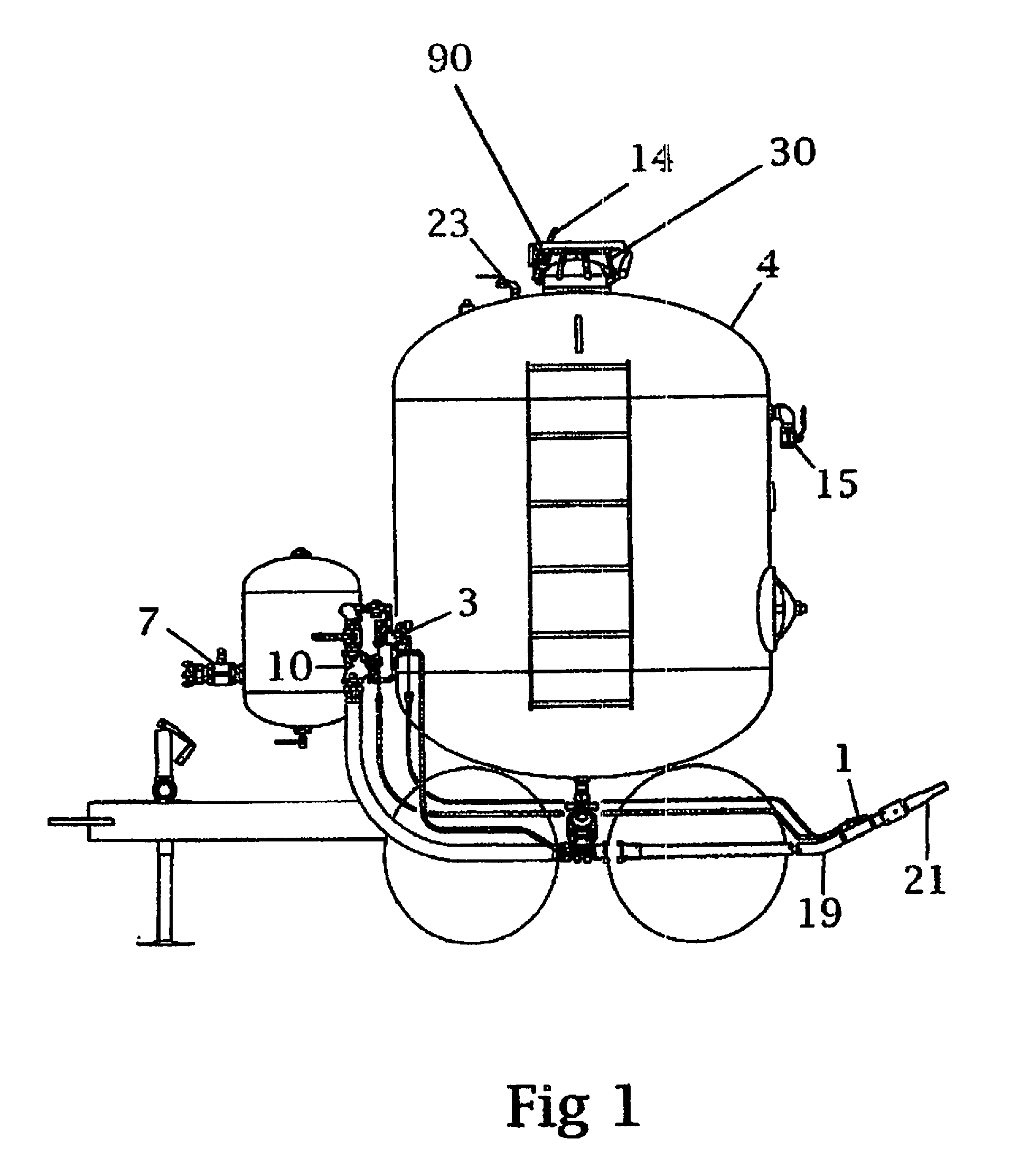
[0030]A typical bulk abrasive blaster is shown in FIG. 1. The pressure tank of pressure vessel 4 includes a pressure inlet valve 7 which is opened to pressurize the tank 4. The abrasive blaster also includes a valve assembly 3 and 10 connected to a deadman valve 1. When the deadman valve is opened, pressurized air flows through the valve assembly for pressurizing the blast line 19 for propelling media from the tank 4, as mixed with the air in the blast line, through the nozzle 21. A blowdown valve 15 is provided for relieving the pressure in the tank 4 when the system is in the off or blowdown condition.

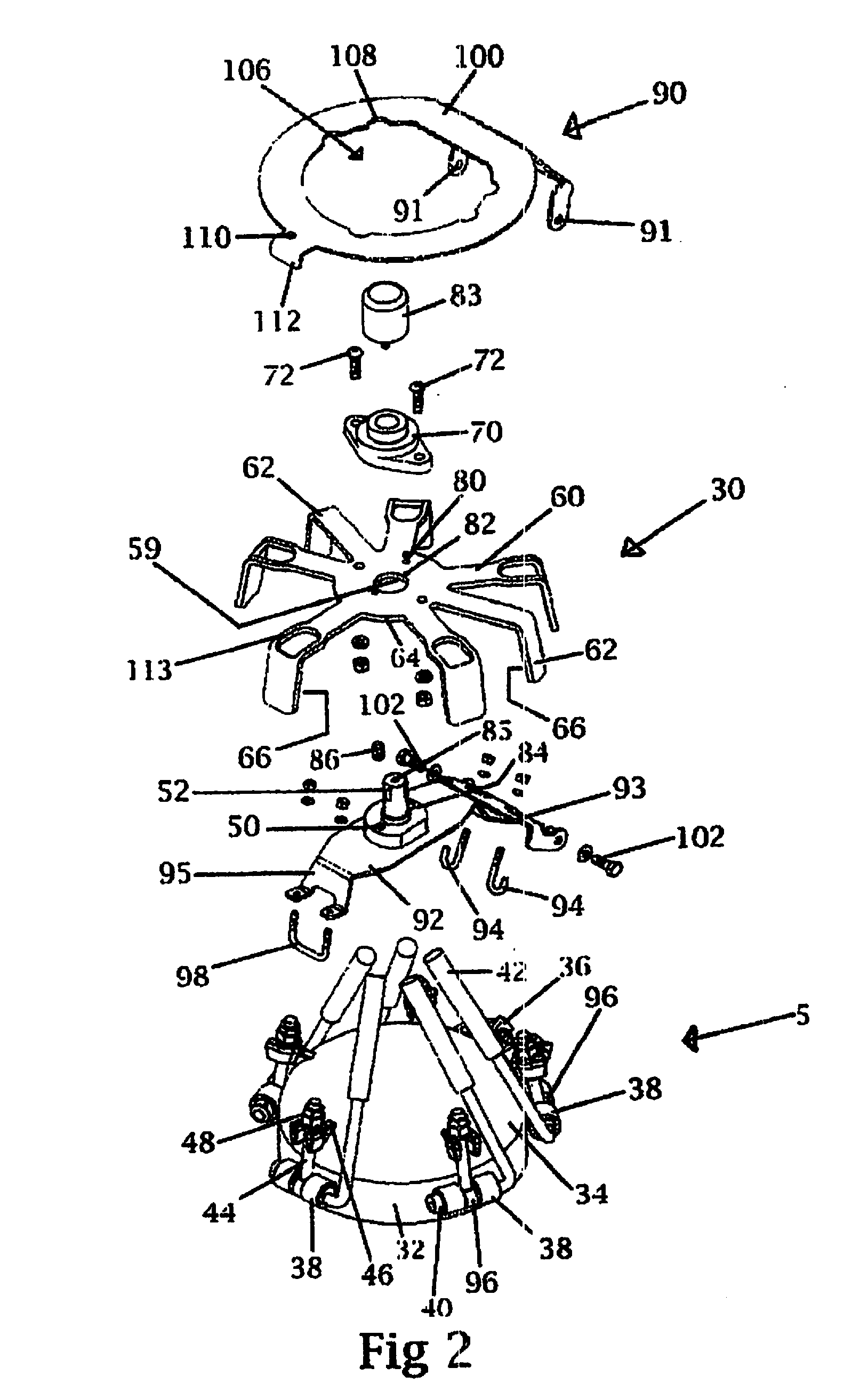
[0031]A closure assembly 5 is mounted on the top of the tank and includes a cam locking assembly 14 and a closure safety interlock 30 in accordance with my aforementioned U.S. Pat. No. 7,850,214. A pressure check indicator valve 23 is typically provided in the tank near the closure assembly 5. The present invention includes a lockout plate assembly 90 secured in position above the cl...


PUM


Abstract

A closure safety interlock system is provided for a pressure vessel having a closure assembly with a primary locking system. The closure safety interlock defines a secondary locking system for assuring that the primary locking system may be opened only by following a proper sequence, thereby minimizing misuse of the primary locking system. The closure safety interlock includes a blocking member movable between an engaged position and a disengaged position for blocking movement of a primary lock when in the engaged position and until a release mechanism in the primary lock has been activated. A mechanism is provided for moving the blocking member from the engaged position to the disengaged position once the release mechanism has been activated. A locking plate is movable between a locked and closed position for prohibiting access to the blocking member and an open position for gaining access to the blocking member.

Description

CROSS-REFERENCE TO RELATED APPLICATION[0001]This application is an improvement over my earlier filed U.S. Pat. No. 7,850,214, issued on Dec. 14, 2010.BACKGROUND OF THE INVENTION[0002]Field of the Invention[0003]The present invention is related to media pressure vessels for bulk abrasive blaster systems and is specifically directed to the closure assembly for such vessels.[0004]Description of the Prior Art[0005]The function of a bulk abrasive blaster system is to provide a controlled mixture of dry abrasive or non-abrasive media and compressed air to a blast nozzle. The abrasive blast stream may be used to prepare the surface being blasted for the application of a protective coating or may be used for simple removal of unwanted surface defects, or other typical blasting operations. The bulk abrasive blaster is one of the components of the abrasive blasting system. The system typically comprises an air compressor, a moisture removal device, the bulk abrasive blaster, a blast line and ...

Claims


Application Information

Patent Timeline
Patent Type & Authority Applications(United States)
IPC IPC(8): F17C13/06B65D55/02B65D51/16B65D50/02
CPCF17C13/06B65D50/02F17C2205/0311B65D51/16B65D55/02B24C9/00
Inventor AMBRIZ, STEVEN RICHARD
Owner AMBRIZ STEVEN RICHARD
Why Eureka
Try Eureka