
Monitor configuration system

a configuration system and monitor technology, applied in the field of monitor configuration system, can solve the problems of medical staff and administrators' challenge in operating flexibility of monitors, and achieve the effect of substantial operational flexibility and operational flexibility

Active Publication Date: 2016-11-17
MASIMO CORP
View PDF5 Cites 292 Cited by
  • Summary
  • Abstract
  • Description
  • Claims
  • Application Information

AI Technical Summary

Benefits of technology

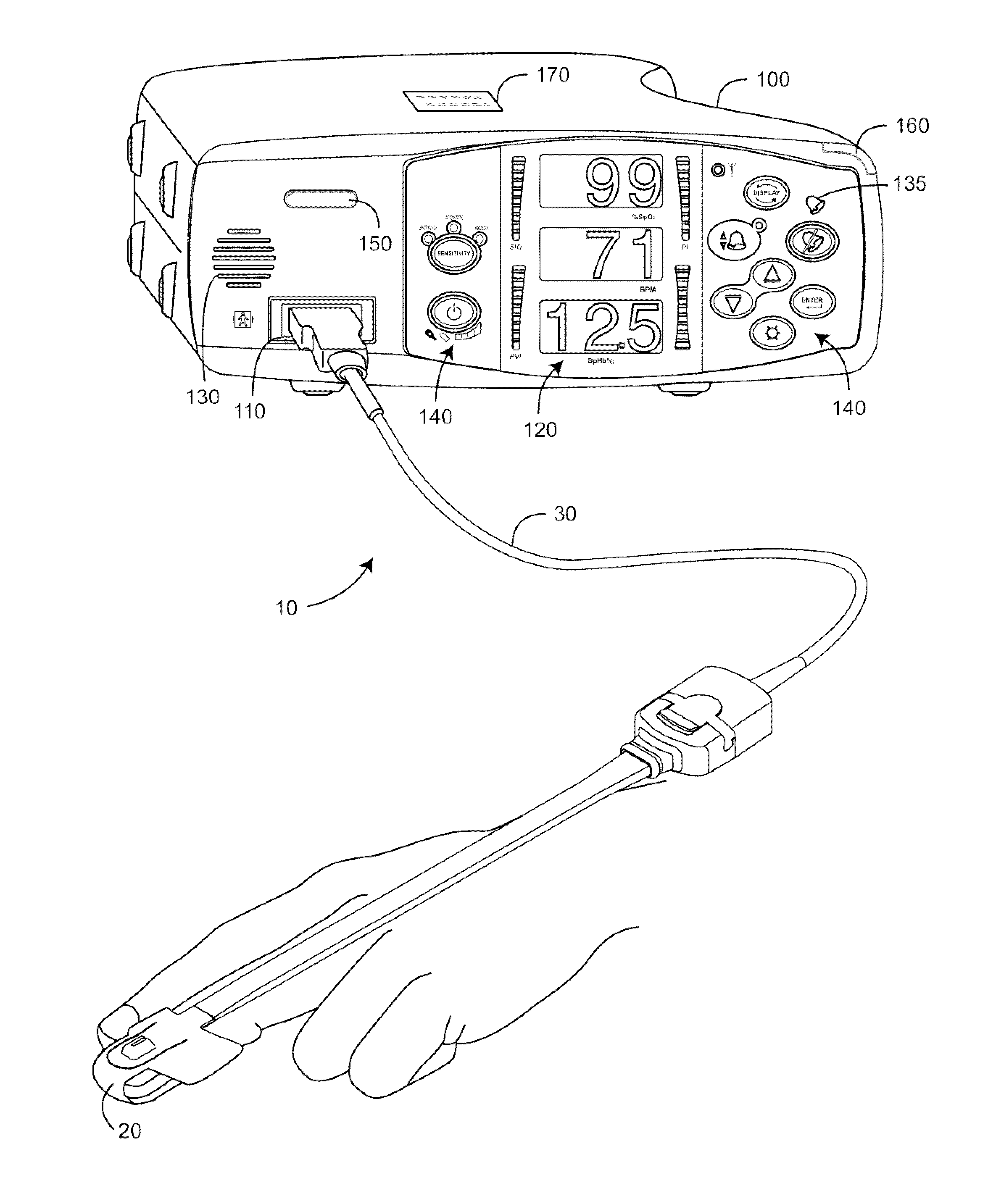
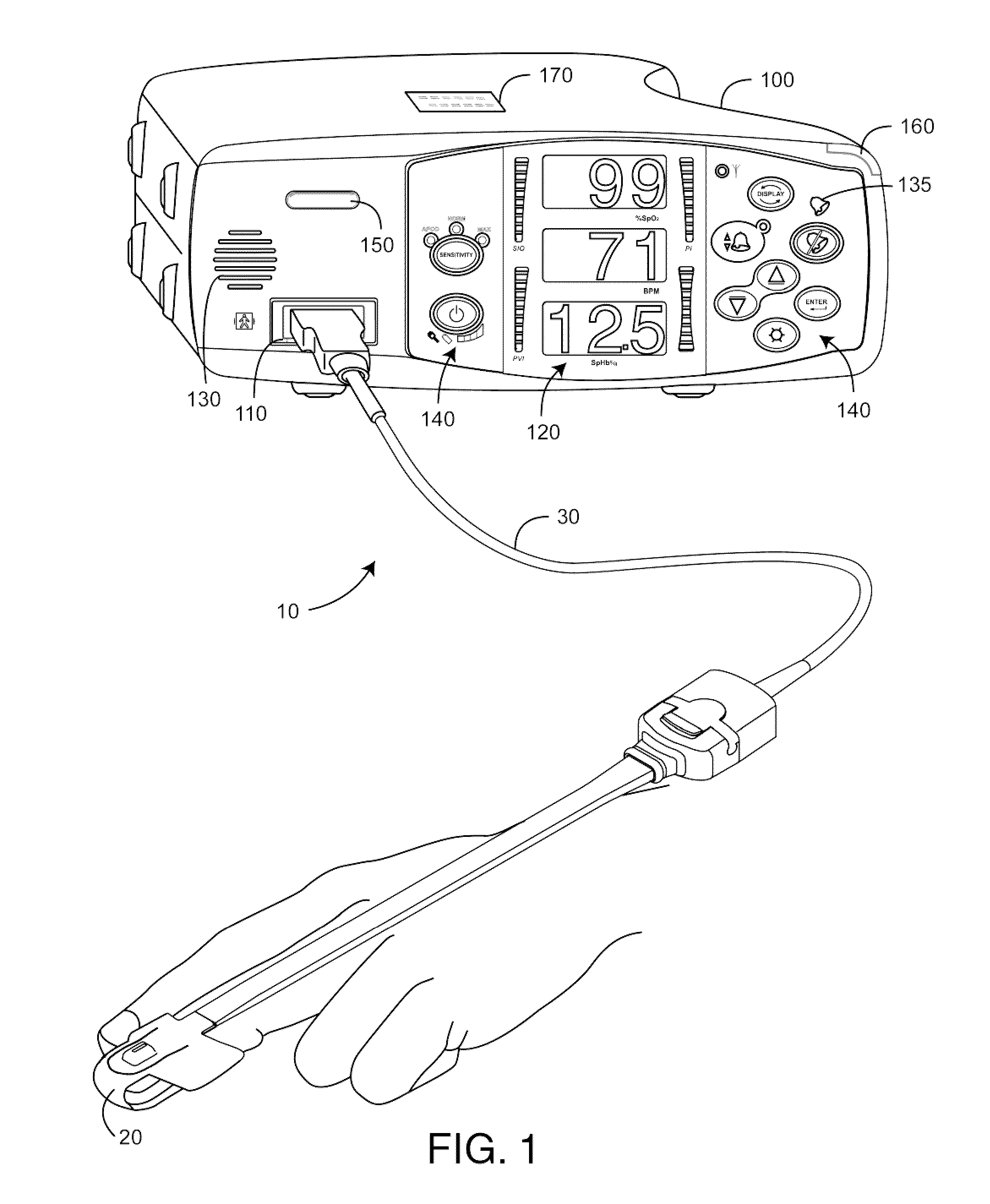
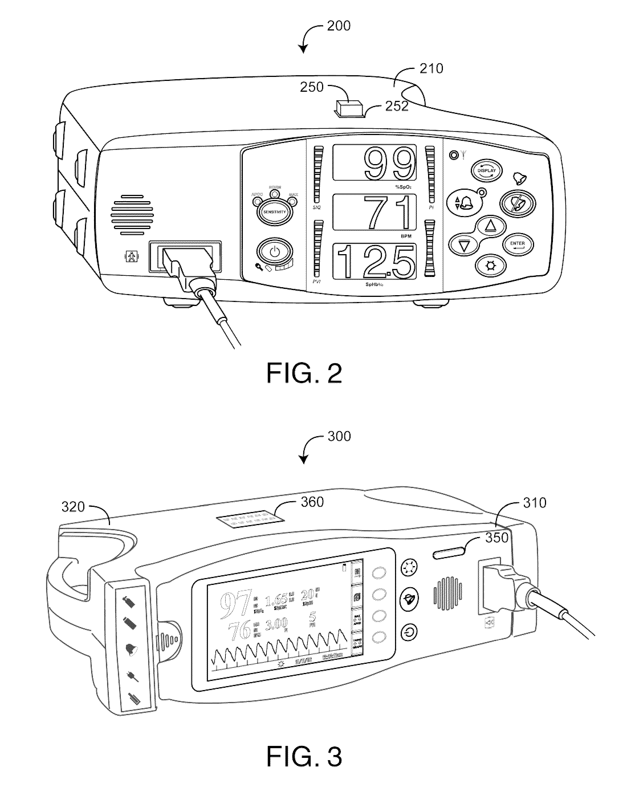
The patent is about a system that allows medical professionals to customize the settings of a noninvasive physiological parameter monitor for their specific needs and patients. The system provides a readily recognizable indication of the current default settings and allows for quick and safe changes to configurations by technical support staff. This system provides medical staff with flexible and customizable monitoring capabilities, which can be tailored to different medical care needs and patient types.

Problems solved by technology

Thus, the operational flexibility of these monitors is a challenge to medical staff and administrators at various facilities, especially if a monitor is used for multiple purposes and patient types or if monitors are frequently moved between locations within a large facility.

Method used


Image

  • Monitor configuration system
  • Monitor configuration system
  • Monitor configuration system

Examples


embodiment 900

[0052]FIG. 9 illustrates a profile programming embodiment 900 having a monitor 910 in communications with a PC 920, notebook, PDA or similar device running a configuration application program (AP). The configuration AP, for example, prompts a user through a menu of monitor default setting options. Once a complete set of options is selected, the PC 920 encodes the data as a user-defined profile and downloads the profile as default settings to the monitor 910. Alternatively, a set of predefined configuration profiles may be provided on a CD ROM 930 or similar storage media. A user then simply selects a desired profile via the PC 920, which downloads that profile to the monitor 910.

[0053]In other embodiments, a monitor 910 may be factory delivered with a variety of configuration profiles, which are selected via configuration codes, menus or similar cataloging functions using front-panel keys 940. A selected profile is associated with a uniquely colored panel light 950 and / or an identif...

embodiment 1000

[0054]FIG. 10 illustrates another profile programming embodiment 1000 having a monitor 1010 in communications with a characterization element 1060 via a programming port 1050. In this embodiment, a user-defined configuration profile is stored in a colored characterization element 1060, such as an EEPROM, EPROM, PROM or similar non-volatile memory device. The monitor 1010 has a specialized programming or configuration port 1050 that electrically and mechanically accepts and communicates with the memory device 1060. The monitor 1010 reads the characterization element 1060 to determine its default settings upon power-up. The characterization element 1060 is specifically colored so as to provide a readily visible indication of the default profile stored within. The user-defined default profile is easily changed by removing one characterization element 1060 from the port 1050 and replacing it with a differently colored characterization element 1060 selected from a preloaded set of memory...


PUM


Abstract

A monitor configuration system which communicates with a physiological sensor, the monitor configuration system including one or more processors and an instrument manager module running on the one or more processors. At least one of the one or more processors communicates with the sensor and calculates at least one physiological parameters responsive to the sensor. The instrument manager controls the calculation, display and / or alarms based upon the physiological parameters. A configuration indicator identifies the configuration profile. In one aspect of the invention, the physiological sensor is a optical sensor that includes at least one light emitting diode and at least one detector.

Description

CROSS-REFERENCE TO RELATED APPLICATIONS[0001]The present application is a continuation of U.S. patent application Ser. No. 12 / 430742, filed Apr. 27, 2009, titled Monitor Configuration System, which claims priority benefit under 35 U.S.C. §119(e) to U.S. Provisional Patent Application Ser. No. 61 / 126,268, filed May 2, 2008, titled Monitor User Interface; and U.S. Provisional Patent Application Ser. No. 61 / 050,205 filed May 3, 2008, titled Monitor Configuration System. All of the above cited provisional applications are hereby incorporated by reference herein.BACKGROUND OF THE INVENTION[0002]Pulse oximetry systems for measuring constituents of circulating blood have gained rapid acceptance in a wide variety of medical applications including surgical wards, intensive care and neonatal units, general wards, home care, physical training, and virtually all types of monitoring scenarios. A pulse oximetry system generally includes an optical sensor applied to a patient, a monitor for proces...

Claims


Application Information

Patent Timeline
Patent Type & Authority Applications(United States)
IPC IPC(8): A61B5/00A61B5/024A61B5/145A61B5/1455
CPCA61B5/7445A61B5/14552A61B5/6826A61B5/02438A61B5/6838A61B5/002A61B2562/227A61B5/746A61B5/7475A61B5/743A61B2560/0276A61B2560/0443A61B5/14546A61B5/0261A61B5/14551A61B5/7495A61B2560/0271
Inventor AL-ALI, AMMAR
Owner MASIMO CORP
Learn More