
LED lighting device and system, and antenna arrangement method

a technology of led lighting and antenna arrangement, which is applied in the direction of point-like light sources, semiconductor devices for light sources, lighting and heating apparatus, etc., can solve the problem of limiting the distance between the antenna and the wireless devi

Active Publication Date: 2016-11-10
SENGLED OPTOELECTRONICS
View PDF5 Cites 6 Cited by
  • Summary
  • Abstract
  • Description
  • Claims
  • Application Information

AI Technical Summary

Benefits of technology

The present patent is about an LED lighting device with improved heat dissipation and protection for the RF antenna. The heat sink body can quickly transmit and dissipate heat produced by its parts, while the heat sink covering further enhances this effect. This makes the device more compact and prevents obstructions that might affect the performance of the RF antenna. As a result, the quality and stability of RF signals sent and received by the antenna are improved.

Problems solved by technology

An antenna of a wireless device has a certain distance limitation.

Method used


Image

  • LED lighting device and system, and antenna arrangement method
  • LED lighting device and system, and antenna arrangement method
  • LED lighting device and system, and antenna arrangement method

Examples


Embodiment Construction

[0017]Reference will now be made in detail to exemplary embodiments of the disclosure, which are illustrated in the accompanying drawings. Wherever possible, the same reference numbers will be used throughout the drawings to refer to the same or like parts.

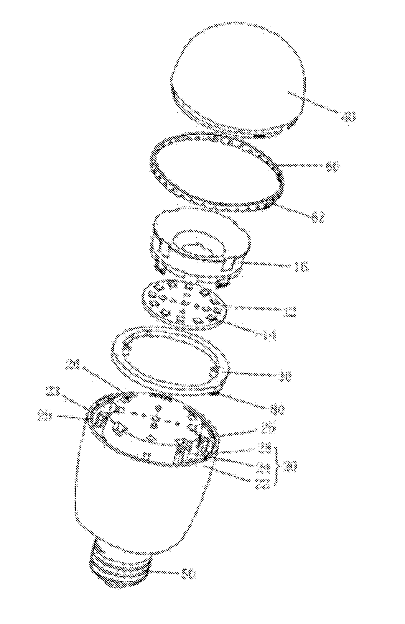
[0018]FIG. 1 illustrates a structure diagram of an exemplary LED lighting device consistent with the disclosed embodiments. FIG. 2 illustrates a breakdown structure diagram of an exemplary LED lighting device consistent with the disclosed embodiments. As shown in FIG. 1 and FIG. 2, the LED lighting device may include a lampshade 40, an LED driving and power supply unit (not shown), an LED light source assembly, a heat sink 20, a control module (not shown), a RF antenna 30, a plastic seat 70, and a lighting base 50. The lighting base 50 may be configured to connect electrically the LED lighting device to an external lighting holder. The plastic seat 70 is sleeved inside the heat sink 20 and is located between the heat sink 20 and t...


PUM


Abstract

A light emitting diode (LED) lighting device is provided. The device includes an LED light source assembly installed on the top of a heat sink body, and an LED driving and power supply unit configured to drive the LED light source assembly and provide electrical power for the LED lighting device. The device also includes a heat sink including the heat sink body and a heat sink covering, where the heat sink covering has an opening; and a plane including the highest point of the top of the heat sink body is higher than a plane including the opening of the heat sink covering. Further, the device includes a radio frequency (RF) antenna installed on periphery of the heat sink body. A plane that includes the highest point of the RF antenna is at the same level or lower than the plane that includes the highest point of the top of the heat sink body.

Description

CROSS-REFERENCES TO RELATED APPLICATIONS[0001]This application is a national stage application under 35 USC §371(c) of PCT Application No. PCT / CN2015 / 093000, entitled “LED Lighting Device and System, and Antenna Arrangement Method,” filed on Oct. 28, 2015, which claims priority to Chinese Patent Application No. 201410829527.5, filed on Dec. 26, 2014. The entire disclosure and contents of the above applications are hereby incorporated by reference herein.FIELD OF THE INVENTION[0002]The present disclosure generally relates to light emitting diode (LED) lighting technology and, more particularly, relates to an LED lighting device and system, and an antenna arrangement method.BACKGROUND[0003]Light emitting diode (LED) is a solid state semiconductor device that can convert electrical energy into visible light. The LED can directly convert electricity into light. LED lighting may generally provide advantages in energy conservation, environmental protection, controllable lighting, solid st...

Claims


Application Information

Patent Timeline
IPC IPC(8): H01Q1/22F21V3/00F21K9/232H01Q1/00H05B37/02F21V23/02F21V1/00F21K9/238F21V29/74F21K9/237
CPCH01Q1/22F21V29/74F21V3/00F21K9/232F21K9/237F21Y2115/10F21V23/02F21V1/00F21K9/238H01Q1/007H05B37/0272F21V23/00F21V23/0435F21Y2101/00F21K9/20F21V29/503H05B47/19
Inventor CHEN, XIAOFEIDENG, XINGMINGSHEN, JINXIANG
Owner SENGLED OPTOELECTRONICS
Learn More