Apparatus and method for non-intrusive off-body measurements in hypersonic flight experiments

a technology of off-body measurement and hypersonic flight, applied in the field of hypersonic flight, can solve the problems of lack of reliable instruments for the accurate measurement of fundamental flight-path data, and the inability to readily obtain fluid-mechanic understanding from standard and commonly known ground-test and computational fluid dynamics, etc., and achieve the effect of improving flexibility for optical measurements

Inactive Publication Date: 2016-11-10
CAIN ALAN B +2
View PDF7 Cites 10 Cited by
  • Summary
  • Abstract
  • Description
  • Claims
  • Application Information

AI Technical Summary

Benefits of technology

The patent describes an apparatus and method for measuring three components of velocity and associated flow angles using optical tracking of a laser-induced breakdown spark. This laser-induced breakdown spectroscopy (LIBS) technique uses a focused laser to create a plasma (spark) that can be tracked using optical sensors. The LIB spark is created in the freestream flow outside of the hypersonic vehicle shock and measures three components of velocity and associated flow angles, providing enhanced flexibility and accuracy in the measurement of flow angles. The method can be operated over a large dynamic range of spark brightness and is able to accurately measure flow velocity and associated flow angles in a blowdown wind tunnel and through a shock with negligible effect on spark formation. The patent demonstrates a novel and effective approach to measuring flow angles in hypersonic vehicles.

Problems solved by technology

This kind of fluid-mechanic understanding cannot be readily obtained from standard and commonly known ground-test and computational fluid dynamics (CFD) efforts alone, since ground-test facilities are not capable of achieving all points in the flight envelope of realistic flight-vehicle designs, while CFD simulations require validation data.
One of the difficulties associated with hypersonic flight-test measurements is the present lack of reliable instrumentation for the accurate measurement of fundamental flight-path data, including windspeed, pitch and yaw.

Method used


Image

  • Apparatus and method for non-intrusive off-body measurements in hypersonic flight experiments
  • Apparatus and method for non-intrusive off-body measurements in hypersonic flight experiments
  • Apparatus and method for non-intrusive off-body measurements in hypersonic flight experiments

Examples


experiment 1

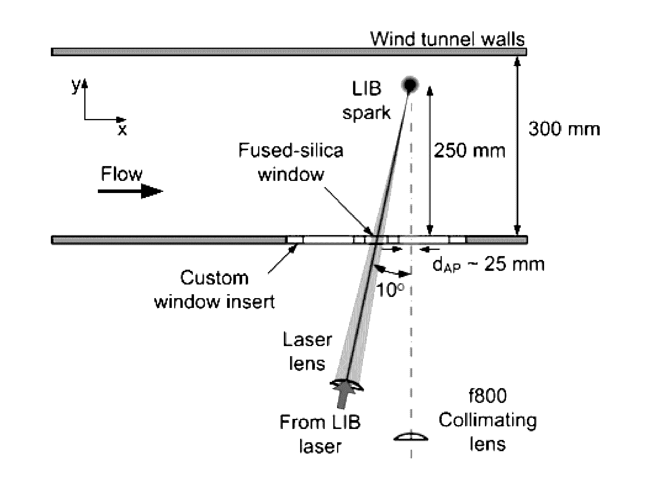
[0086]Testing of aero-optical instrument 100 was performed in a wind tunnel with a blowdown configuration comprising: test-section dimensions of 1 ft.×1 ft.; maximum Mach number of 4.38; and maximum test-section total pressure of 1.7 MPa. The air storage consists of six 25.5 m3 tanks that can be pumped to a pressure of 4 MPa, giving up to 7 min of total run time depending on test conditions. The stored air is first dried to −45° C. dew point and then heated to around 38° C. in order to prevent water condensation, ice formation and / or liquefaction in the test section.

[0087]The measurements were performed at test-section Mach numbers of 3 and 4.38. Tunnel conditions for all tests performed are summarized below in Table 1. The boundary-layer thickness δ is dictated primarily by the length of the nozzle block for the test Mach number and was verified by Schlieren and theoretical calculations. The standard-atmosphere altitude shown in Table 1 is based on the test-section density, which h...


PUM


Abstract

An “air-data probe” system measures at least one component of freestream velocity by tracking the motion of a laser-induced breakdown (“LIB”) spark created in a freestream flow. Neutral density filters are positioned or deployed so that the brightness of the initial LIB spark doesn't over saturate the LIB sensor system. This allows for more consistent tracking of the LIB spark throughout the duration of the LIB spark, including the later stages where the LIB spark is not nearly as bright as the initial LIB spark, thereby allowing all or substantially all of the light generated by the LIB spark to reach the sensors. This provides for enhanced visibility and more accurate detection of the LIB spark over time and as air density changes.

Description

STATEMENT REGARDING GOVERNMENT SPONSORED RESEARCH[0001]The United States Government has a paid-up license in this invention and the right in limited circumstances to require the patent owner to license others on reasonable terms provided for by the terms of grand numbers FA9550-13-C-0010 and FA9550-11-C-0091 awarded by the United States Air Force.BACKGROUND OF THE INVENTION[0002]1. Technical Field[0003]The present invention relates generally to hypersonic flight and more specifically relates to the method of making precise measurements of high-speed flow for hypersonic flight testing environments with reduced uncertainty.[0004]2. Background Art[0005]Several development programs for new hypersonic flight vehicles are currently underway. To facilitate these programs, hypersonic test programs are being conducted to enhance understanding of high-speed flows so as to enable improved prediction and design capabilities. A key objective of hypersonic flight-testing programs is the ability t...

Claims


Application Information

Patent Timeline
Patent Type & Authority Applications(United States)
IPC IPC(8): G01M9/06G01F1/66G01F1/7086
CPCG01F1/661G01M9/06G01M9/065G01M9/067G01F1/7086G01P5/26G01F1/712
Inventor CAIN, ALAN B.GORDEYEV, STANISLAVRENNIE, R. MARK
Owner CAIN ALAN B
Why Eureka
Try Eureka