
Techniques for percutaneous mitral valve replacement and sealing

a technology of mitral valve and percutaneous mitral valve, which is applied in the field of prosthetic valves, can solve the problems of decreased cardiac output and increased total stroke volume, and achieve the effects of facilitating radial facilitating the expansion and facilitating the compression of the prosthetic valv

Active Publication Date: 2016-11-10
CARDIOVALVE LTD
View PDF46 Cites 127 Cited by
  • Summary
  • Abstract
  • Description
  • Claims
  • Application Information

AI Technical Summary

Benefits of technology

The patent describes an apparatus that can expand and compress a prosthetic valve using control filaments. The apparatus can be used to repair damaged native valves or aortic valves through a minimally invasive surgery. The patent also describes the components of the apparatus and how they can be coupled together to facilitate the replacement of a damaged valve. The technical effect of the invention is to provide a reliable and effective tool for the repair or replacement of damaged valves.

Problems solved by technology

Regurgitation of blood from the ventricle into the atrium results in increased total stroke volume and decreased cardiac output, and ultimate weakening of the ventricle secondary to a volume overload and a pressure overload of the atrium.

Method used


Image

  • Techniques for percutaneous mitral valve replacement and sealing
  • Techniques for percutaneous mitral valve replacement and sealing
  • Techniques for percutaneous mitral valve replacement and sealing

Examples


Embodiment Construction

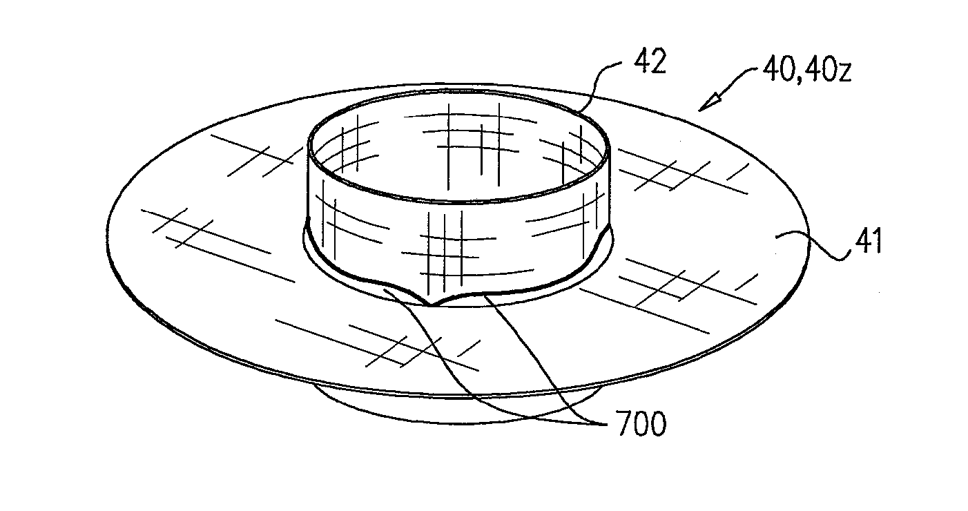
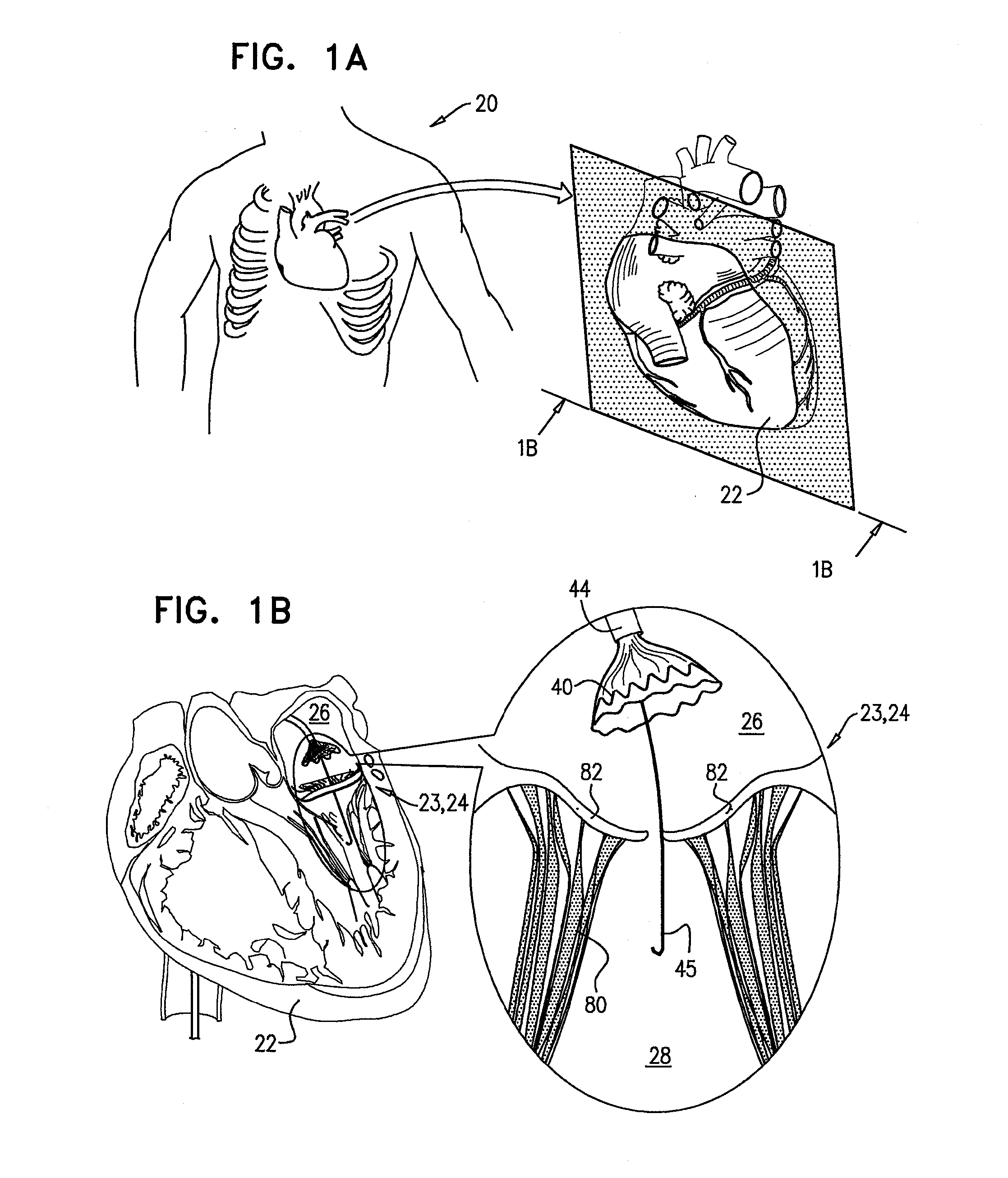
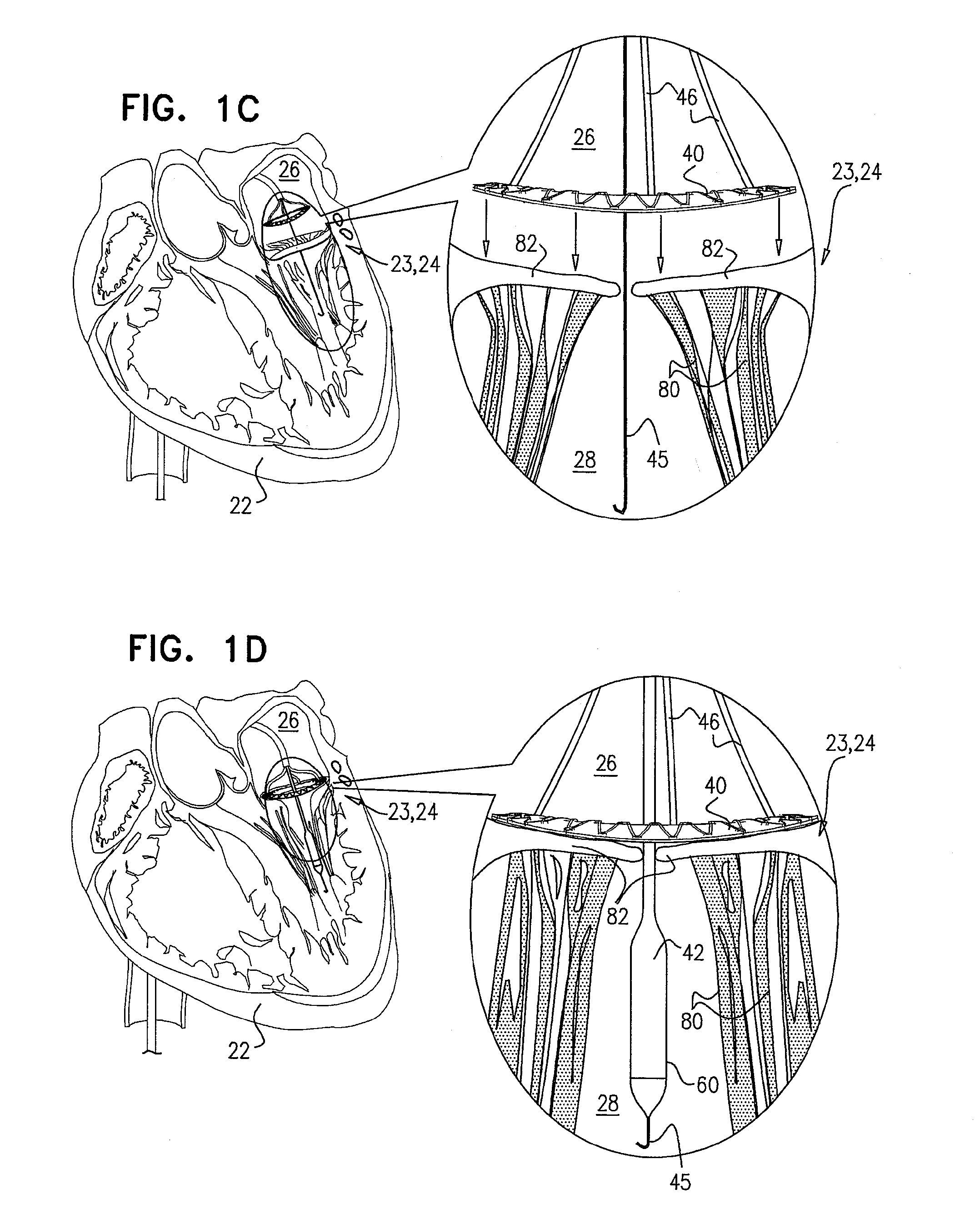
[0159]Reference is made to FIGS. 1A-H, which are schematic illustrations of sequential steps in the implantation in a native heart valve 23 of the heart 22 of a subject 20 of an implant 30, comprising (1) a first prosthetic valve component, i.e., prosthetic valve support 40, and (2) a second prosthetic valve component, i.e., a prosthetic valve 42, in accordance with some applications of the present invention. For such applications of the present invention, native valve 23 includes a native mitral valve 24 by way of illustration and not limitation; the scope of the present invention includes implanting implant 30 in other valves of the heart (e.g., the tricuspid valve, the pulmonary valve, or the aortic valve). FIG. 1A illustrates a cross-section through heart 22 of the subject which is used throughout FIGS. 1B-G to illustrate the implantation procedure. As shown in the cross-sectional illustration, native mitral valve 24 includes native leaflets 82, which are supported by native cho...


PUM


Abstract

Apparatus for use at a native heart valve of a subject is described. For some applications, the apparatus comprises a prosthetic valve support, configured (a) to be implanted at the native valve, (b) to facilitate, at a first period, implantation at the native valve of a first prosthetic valve, and (c) to facilitate, at a second period, implantation at the native valve of a second prosthetic valve. Other embodiments are also described.

Description

CROSS-REFERENCES TO RELATED APPLICATIONS[0001]This application claims priority from:[0002]U.S. 61 / 515,372 to Gross, filed Aug. 5, 2011;[0003]U.S. 61 / 525,281 to Gross, filed Aug. 19, 2011;[0004]U.S. 61 / 537,276 to Gross, filed Sep. 21, 2011;[0005]U.S. 61 / 555,160 to Gross, filed Nov. 3, 2011;[0006]U.S. 61 / 588,892 to Gross, filed Jan. 20, 2012; and[0007]U.S. Ser. No. 13 / 412,814 to Gross, filed Mar. 6, 2012, all of which are incorporated herein by reference; and[0008]this application is a Continuation-In-Part of U.S. Ser. No. 13 / 412,814 to Gross, filed Mar. 6, 2012.[0009]This application is related to a PCT application to Gross, entitled, “Percutaneous mitral valve replacement and sealing,” filed on even date herewith.FIELD OF THE INVENTION[0010]Some applications of the present invention relate in general to valve replacement. More specifically, some applications of the present invention relate to prosthetic valves for replacement of a cardiac valve.BACKGROUND[0011]Ischemic heart disease...

Claims


Application Information

Patent Timeline
Patent Type & Authority Applications(United States)
IPC IPC(8): A61F2/24
CPCA61F2/2418A61F2/2409A61F2/2433A61F2250/0069A61F2/2436A61F2220/0016A61F2250/006A61F2/2439A61F2/2442A61F2/848A61F2220/0025A61F2220/0091A61F2230/0013A61F2230/005A61F2230/0054A61F2230/0078A61F2250/0015A61F2250/0071
Inventor GROSS, YOSSIHACOHEN, GILMILLER, ERANZIPORY, YUVALREICH, TALKUTZIK, MEIRNEEMAN, ROTEM
Owner CARDIOVALVE LTD
Learn More