High efficiency video coding device and method based on reference picture type
a video coding and reference picture technology, applied in the field of image processing devices and image processing methods, can solve problems such as unoptimized macroblock size of 1616 pixels, and achieve the effect of suppressing the decrease in encoding efficiency
- Summary
- Abstract
- Description
- Claims
- Application Information
AI Technical Summary
Benefits of technology
Problems solved by technology
Method used
Image
Examples
first embodiment
1. First Embodiment
[0157]In image encoding such as AVC (Advanced Video Coding) or HEVC (High Efficiency Video Coding), motion prediction using correlation in the temporal direction (between frames) is performed.
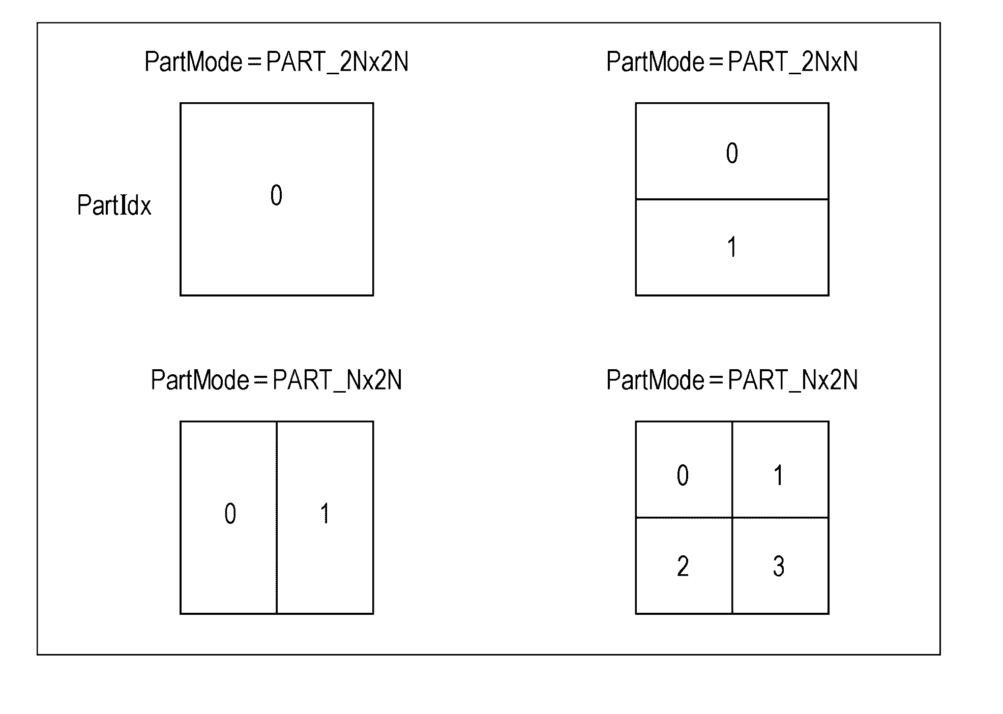
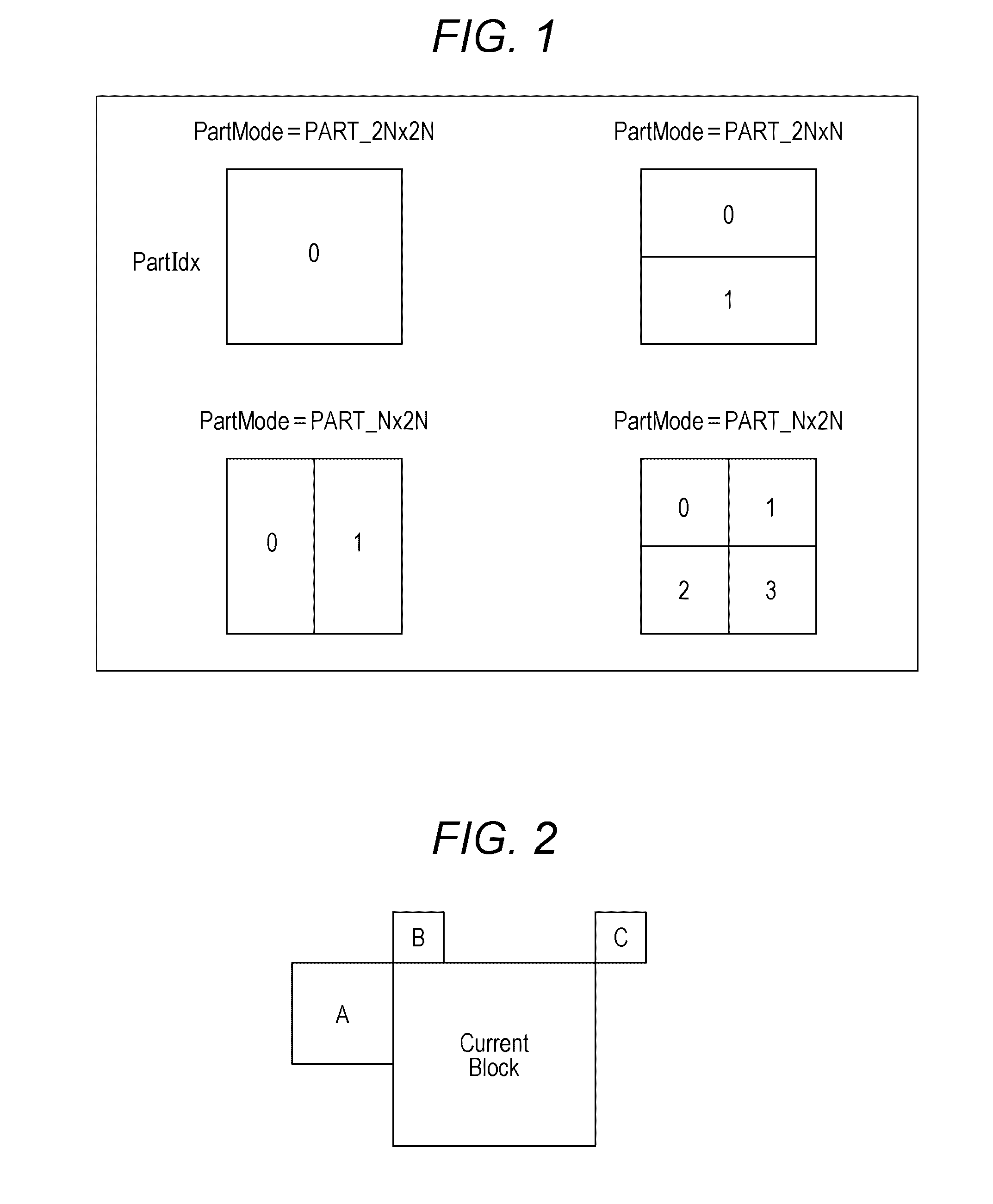
[0158]The AVC defines layered blocks such as macroblocks or sub-macroblocks as processing units of such a prediction process, and the HEVC defines coding units (CUs).
[0159]The CU which is also called a coding tree block (CTB) is a partial region of a picture-base image, which plays the same role as the macroblock in the AVC. The size of the macroblock is fixed to 16×16 pixels whereas the size of the CU is not fixed but is designated in image compression information in respective sequences.
[0160]For example, the largest size (LCU: Largest Coding Unit) and the smallest size (SCU: Smallest Coding Unit) of the CU are defined in a sequence parameter set (SPS) included in output encoded data.
[0161]Each LCU can be split into CUs of the smaller size that is not small...
second embodiment
2. Second Embodiment
Image Decoding Device
[0366]FIG. 31 is a block diagram illustrating a main configuration example of an image decoding device which is an image processing device. An image decoding device 300 illustrated in FIG. 31 is a device that corresponds to the image encoding device 100 of FIG. 11. That is, the image decoding device 300 decodes the encoded data (bit stream), which is generated through encoding a multi-view image by the image encoding device 100, according to a decoding method corresponding to the encoding method of the image encoding device 100 to obtain a decoded multi-view image.
[0367]As illustrated in FIG. 31, the image decoding device 300 includes an accumulation buffer 301, a lossless decoding unit 302, an inverse quantization unit 303, an inverse orthogonal transform unit 304, an arithmetic unit 305, a loop filter 306, a screen rearrangement buffer 307, and a D / A converter 308. Moreover, the image decoding device 300 includes a decoded picture buffer 30...
third embodiment
3. Third Embodiment
Point
[0423]In the case of multi-view images, the positions of images are offset between views so that a parallax occurs. Thus, when a block in the view direction is selected, even if a block at the same position is selected (referred to), the prediction accuracy of the predicted image may decrease and there is a possibility that it is not possible to create an appropriate predictive vector.
[0424]Thus, when a block in the view direction is selected in order to generate a predictive vector, a block at a shifted position is selected. That is, the predictive vector is generated using a vector of such a region that is located at the same position as the current region in a state where the position of an image of the same time as the current region is shifted.
[0425]The shift amount is calculated in a predetermined order from the parallax vector of the neighboring block. By using the same order in both an encoding-side device and a decoding-side device, the same predicti...
PUM
 Abstract
Description
Claims
Application Information
 - R&D
- Intellectual Property
- Life Sciences
- Materials
- Tech Scout
- Unparalleled Data Quality
- Higher Quality Content
- 60% Fewer Hallucinations
Browse by: Latest US Patents, China's latest patents, Technical Efficacy Thesaurus, Application Domain, Technology Topic, Popular Technical Reports.
© 2025 PatSnap. All rights reserved.Legal|Privacy policy|Modern Slavery Act Transparency Statement|Sitemap|About US| Contact US: help@patsnap.com


