
Turbomachine with a coating, use of a plastic for coating and method for coating the turbomachine

a technology for turbomachines and plastics, applied in the field of turbomachines, can solve problems such as new construction, casing deformation, stress in materials, etc., and achieve the effects of reducing the density of coatings, improving thermal barrier properties, and reducing the weight of coatings

Inactive Publication Date: 2016-10-06
SIEMENS AG
View PDF5 Cites 4 Cited by
  • Summary
  • Abstract
  • Description
  • Claims
  • Application Information

AI Technical Summary

Benefits of technology

This patent is about a way to insulate the inner part of a turbomachine using a special coating. This coating is applied to the inner casing and can be easily produced. It is made of a base material that has low thermal conductivity and good insulation properties, as well as low weight and good mechanical properties. The coating can also contain hollow balls which improve its thermal barrier properties and make it more stable and cost-effective. This method simplifies the production of the insulation and reduces the risk of deformation of the inner casing, while also reducing the thermal load on the outer casing. Overall, this patent provides a simple and efficient way to insulate turbomachines.

Problems solved by technology

This results in stresses within the material, which can lead to casing deformations.
The drawback of sheet metal constructions is that they have to be constructed anew for each series of turbines.
In this context, there is a further drawback in that mounting the sheet metal constructions is complex and time-consuming.
In addition, vibrations and wear can lead to individual metal sheets tearing off from the construction and to screw connections for the metal sheets coming loose, which has a negative effect on stability, thermal insulation and thus on the efficiency of the turbine.

Method used


Image

  • Turbomachine with a coating, use of a plastic for coating and method for coating the turbomachine
  • Turbomachine with a coating, use of a plastic for coating and method for coating the turbomachine

Examples


Embodiment Construction

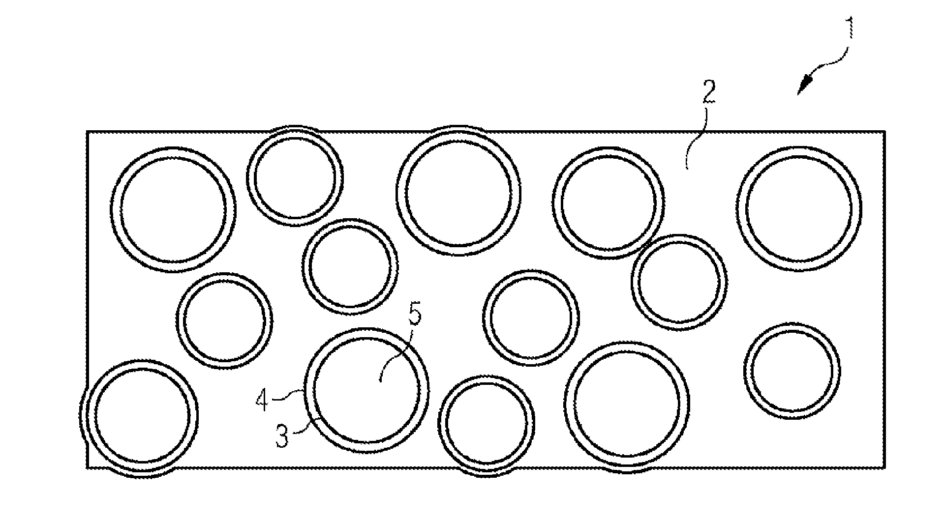
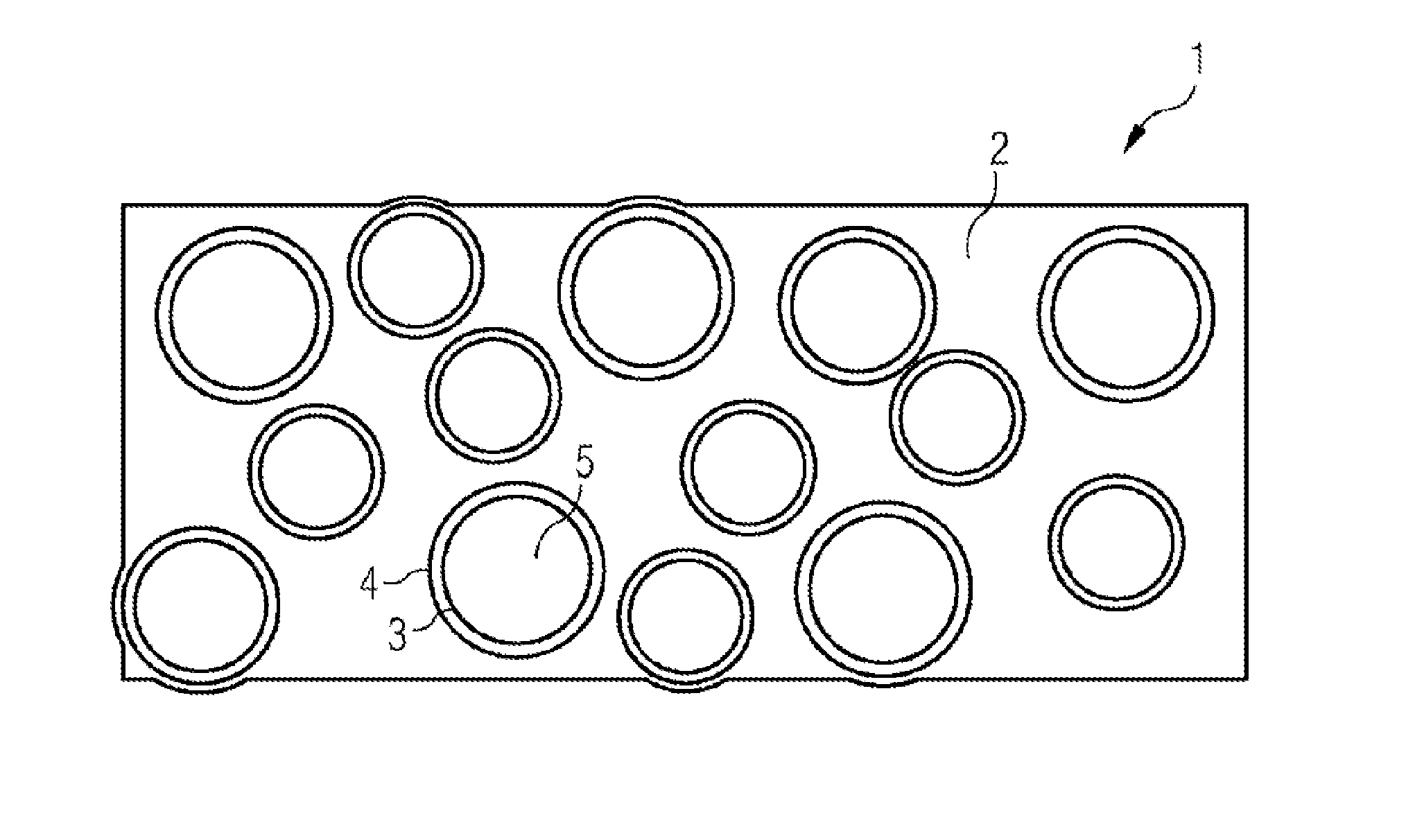
[0021]The material of the hollow balls 3 embedded in the matrix 2 can in that context include organic material, in particular the polymers listed above, or also of polyacrylate, but also of inorganic materials, in particular glass or ceramic.

[0022]In that context, an essential factor which influences the thermal barrier effect and weight of the coating 1 is the size of the hollow balls 3. The larger the hollow balls 3, the greater the degree of filling and accordingly the lower the weight of the coating 1 and also the lower the heat-conducting properties. However, the size of the hollow balls 3 should be chosen so as not to jeopardize the mechanical strength of the coating. The size of the hollow balls 3 is defined by their diameter. It is advantageous for the diameter of the hollow balls to be between 5 μm and 1000 μm, more advantageous between 10 μm and 500 μm, even more advantageous between 20 μm and 300 μm and even more advantageous still between 25 μm and 200 μm.

[0023]In one em...


PUM

PropertyMeasurementUnit
Diameteraaaaaaaaaa
Diameteraaaaaaaaaa
Fractionaaaaaaaaaa

Abstract

A turbomachine includes an inner housing which radially defines the flow channel of the turbomachine. A thermal barrier coating is arranged about the inner housing. The thermal barrier coating of the inner housing is made of microporous plastic coating which can be added to hollow spheres made of different materials and have different sizes. A method for applying a thermal barrier coating to the inner casing of a turbomachine includes preparing a material having a base material which has a microporous plastic; coating the outside of the wall of the inner casing by applying the base material to the inner casing; and curing the applied material, thus forming the thermal barrier coating.

Description

CROSS REFERENCE TO RELATED APPLICATIONS[0001]This application is the US National Stage of International Application No. PCT / EP2014 / 069875 filed Sep. 18, 2014, and claims the benefit thereof. The International Application claims the benefit of European Application No. EP13191892 filed Nov. 7, 2013. All of the applications are incorporated by reference herein in their entirety.FIELD OF INVENTION[0002]The invention relates to a turbomachine which comprises an inner casing radially bounding the flow duct, wherein a coating is arranged around the inner casing, and also to the use of a plastic for coating and to a method for coating the turbomachine.BACKGROUND OF INVENTION[0003]The term turbomachine relates here to a turbine, in particular to a gas turbine, a steam turbine and especially to a low-pressure turbine. In the further context of the description of the invention, the term turbine is to be understood as synonymous with steam turbine or low-pressure turbine.[0004]Steam turbines ca...

Claims


Application Information

Patent Timeline
IPC IPC(8): F01D25/14F01D25/00F01D25/24
CPCF01D25/145F01D25/24F01D25/005F05D2220/31B05D1/28F05D2300/5023F05D2300/432F05D2300/44F05D2300/20F05D2230/90F05D2300/43F05D2300/21F05D2300/2102F01D25/26F02K1/822F05D2250/241F05D2300/5024F05D2300/514F05D2300/48
Inventor ETTLER, MANUELKOCDEMIR, BORALITINSKY, ALEXANDERMASHKIN, ANDREYMINNINGER, DIETERZIMMERMANN, ADAM
Owner SIEMENS AG
Learn More