Optically based devices, systems, and methods for neuromodulation stimulation and monitoring

Inactive Publication Date: 2016-10-06
ZYVEX LABS LLC
View PDF3 Cites 13 Cited by
  • Summary
  • Abstract
  • Description
  • Claims
  • Application Information

AI Technical Summary

Benefits of technology

The present patent discloses small-sized neuromodulation implants that can provide precise targeted electrical stimulation, blocking, and monitoring / recording of physiological responses. The implants have the ability to measure the physiological responses associated with therapeutic actions and modify stimulation parameters after implantation. The small size of the implants eliminates the need for traditional surgery, minimizes adverse tissue response, discomfort, and post-surgery complications, and allows for a high temporal and spatial resolution of stimulating and monitoring large nerve bundles. The implants can communicate with external devices without the need for a wired connection and do not require batteries for functioning. The patent also describes a modular neuromodulation system where multiple implants can be implanted and operate individually or coordinated with each other.

Problems solved by technology

However, if the power source becomes disconnected, stops holding a charge, or otherwise stops working properly, a further surgery is required to replace the power source.
However, this approach requires an opening through the skin that can be uncomfortable for the patient, prone to infection, and prone to causing scar tissue along the length of the conductors within the patient.
The very high difference between the elasticity of human tissue and the constrained electrode lead(s) can also cause addition scaring.

Method used


Image

  • Optically based devices, systems, and methods for neuromodulation stimulation and monitoring
  • Optically based devices, systems, and methods for neuromodulation stimulation and monitoring
  • Optically based devices, systems, and methods for neuromodulation stimulation and monitoring

Examples


Embodiment Construction

[0034]The detailed description set forth below, in connection with the appended drawings, is intended as a description of various configurations and is not intended to represent the only configurations in which the concepts described herein may be practiced. The detailed description includes specific details for the purpose of providing a thorough understanding of the various concepts. However, it will be apparent to those skilled in the art that these concepts may be practiced without these specific details. In some instances, well-known structures and components are shown in block diagram form in order to avoid obscuring such concepts.

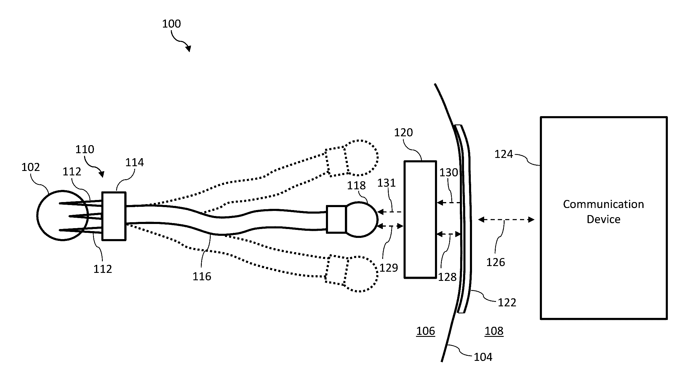
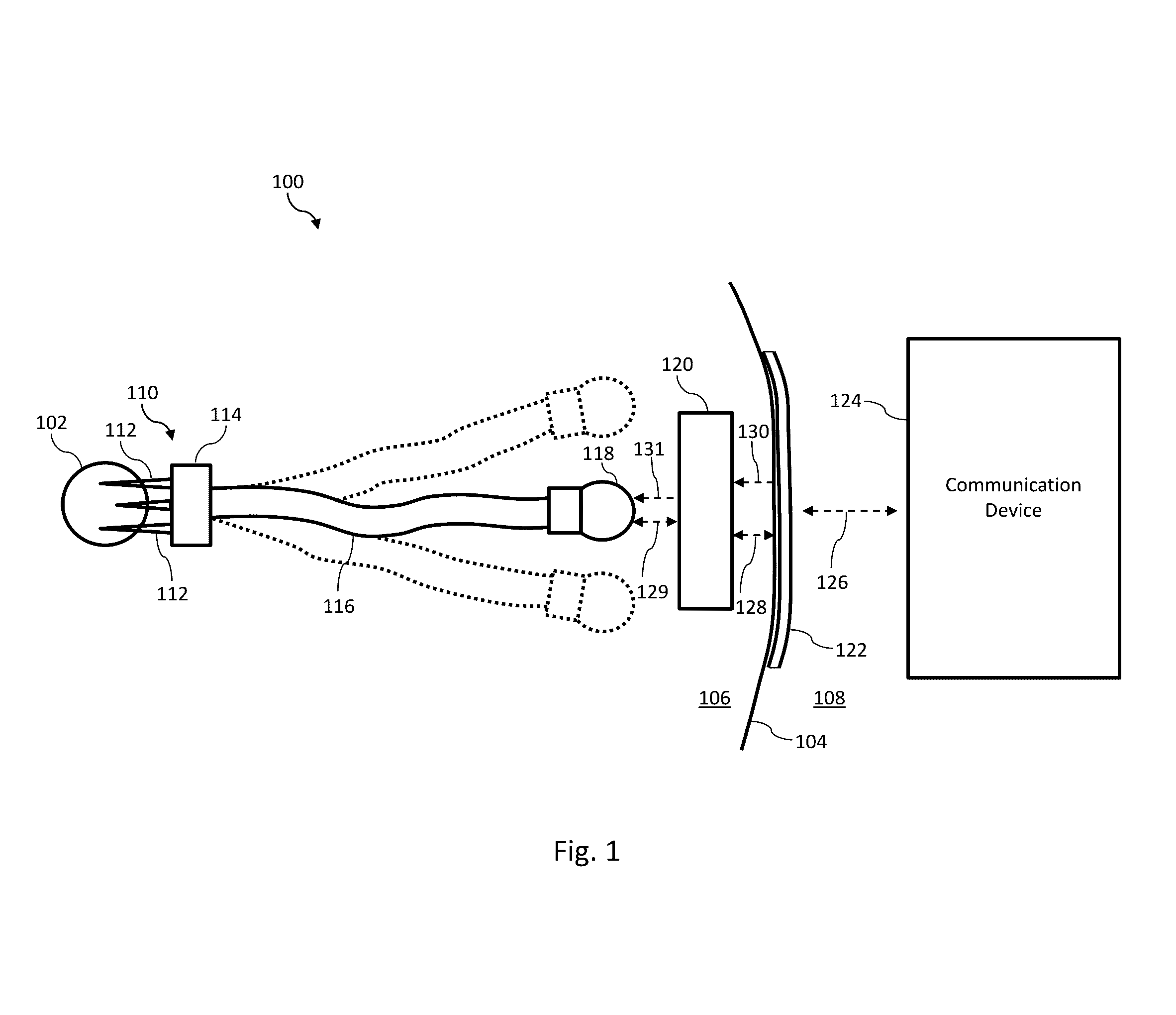
[0035]FIG. 1 is a diagram of an exemplary neuromodulation system 100 according to embodiments of the present disclosure. The neuromodulation system 100 is utilized to stimulate and / or monitor a nerve 102 of a patient. Generally, the nerve 102 is representative of a nerve or nerve bundle in any portion of the body, including spinal cord, deep brain, v...


PUM


Abstract

Devices, systems, and methods for neuromodulation are provided. For example, a neuromodulation system is disclosed that comprises an implantable neuromodulation module having a photodiode configured to generate electrical current in response to receiving light from an optical fiber; an optical transceiver; and at least one electrode configured to provide electrical stimulation to a nerve utilizing the electrical current generated by the photodiode. As another example, a method of neuromodulation is disclosed that comprises receiving light at a photodiode of a neuromodulation module and generating electrical current in response to receiving the light; and providing, via at least one electrode of the module positioned within the patient, electrical stimulation to a nerve of the patient utilizing the electrical current generated by the photodiode.

Description

CROSS-REFERENCE TO RELATED APPLICATIONS[0001]This application claims priority to and the benefit of U.S. Provisional Patent Application No. 62 / 143,500, filed Apr. 6, 2015, which is hereby incorporated by reference in its entirety.TECHNICAL FIELD[0002]The present disclosure relates to neuromodulation and, more particularly, to devices, systems, and methods for electrically stimulating nerve(s), blocking nerve signaling, and / or monitoring nerve activity.BACKGROUND[0003]Neuromodulation continues to increase as an adopted technique for treating of a wide variety of medical conditions. For example, neuromodulation devices for spinal cord stimulation have been utilized for the management of pain. Similarly, neuromodulation devices for deep brain stimulation have been utilized for the treatment of Parkinson's, essential tremor, dystonia, and other disorders. Neuromodulation devices for vagus nerve stimulation have been utilized to control seizures, such as those associated with epilepsy. A...

Claims


Application Information

Patent Timeline
IPC IPC(8): A61N1/378A61N1/372A61N1/36
CPCA61N1/3787A61N1/37223A61N1/3605A61N1/37217H02J50/30H04B10/1143H04B10/40H04B10/807G02B6/428G02B6/4246G02B6/4249H02J2310/23G02B6/42G02B6/00H04B10/00H04B13/005
Inventor SAINI, RAHUL
Owner ZYVEX LABS LLC
Why Eureka
Try Eureka