
Flexible substrate, OLED device and defect detecting method for the same

Active Publication Date: 2016-09-29
BOE TECH GRP CO LTD
View PDF4 Cites 10 Cited by
  • Summary
  • Abstract
  • Description
  • Claims
  • Application Information

AI Technical Summary

Benefits of technology

The present invention provides a flexible substrate and an OLED device with high detection efficiency and accuracy in detecting defects. By adding a crack detection layer made of electrochromic material to the flexible substrate, it becomes easier to determine whether defects of the flexible substrate and the OLED device are caused by a crack in the barrier layer. Compared to the prior art method of observing a sample with a magnifying glass, the shortcoming of difficulty in finding defect points is overcome, and time is saved. This enables efficient control of defect producing process steps and improves the rate of qualified products of the flexible substrate and the OLED device.

Problems solved by technology

At present, the barrier film is generally formed by means of depositing a silicon nitride material (SiNx) and a silicon oxide material (SiOx) in the flexible substrate; because SiNx and SiOx are both inorganic materials, cracks are easily produced in the bending process; moreover, to prevent the water oxygen from permeating into the OLED device through pin holes, SiNx and SiOx need to have certain thicknesses to achieve the effect of blocking water and oxygen, whereas the probability of producing cracks is further increased due to the increase of thicknesses of SiNx and SiOx films.
The barrier film cracks may lead to defects of the OLED device.
Generally, when the OLED device has a defect, the defect of a thin film transistor (TFT) in the OLED device is easily determined from the change of electrical performance; whereas the defects caused by cracks of the barrier film in the OLED device need to be observed with a microscope, and observation by using the microscope has the problems that sample preparation is complex, a defect point is difficult to be found, a long time is consumed and the like, leading to not only low detection efficiency, but also low accuracy of detection result, and thus the process step causing the defect cannot be effectively controlled, thereby resulting in a relatively low rate of qualified product of the OLED device.

Method used


Image

  • Flexible substrate, OLED device and defect detecting method for the same
  • Flexible substrate, OLED device and defect detecting method for the same
  • Flexible substrate, OLED device and defect detecting method for the same

Examples


first embodiment

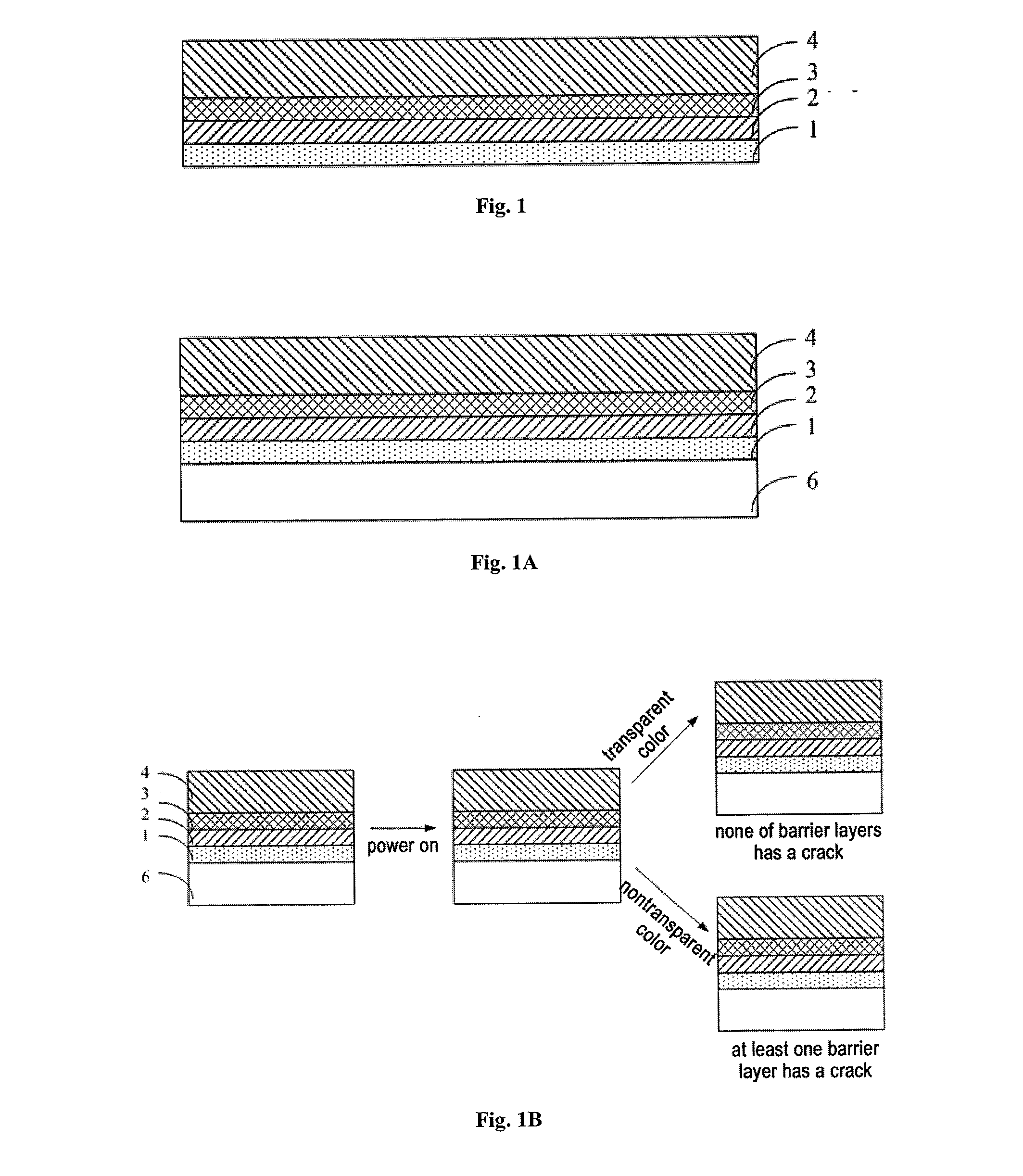
[0045]This embodiment provides a flexible substrate; the flexible substrate includes a bottom plate and a barrier layer arranged above the bottom plate and further includes a crack detection layer, which is arranged adjacent to the barrier layer; the crack detection layer produces a crack when the barrier layer produces a crack; and the color of the crack detection layer with a crack is different from that of the crack detection layer without a crack in a power-on state.

[0046]As shown in FIG. 1, the barrier layer includes a first barrier layer 2 and a second barrier layer 4. The flexible substrate further includes a crack detection layer 3, and in this embodiment, the crack detection layer 3 is arranged between the first barrier layer 2 and the second barrier layer 4. Due to the particularity of the material (see the following description) forming the crack detection layer 3, when the first barrier layer 2 and / or the second barrier layer 4 produce a crack, the crack detection layer ...

second embodiment

[0056]This embodiment provides a flexible substrate, and differs from the first embodiment in that the crack detection layer 3 in the flexible substrate of this embodiment is only adjacent to the first barrier layer 2.

[0057]As shown in FIG. 2, the first barrier layer 2 is closer to the bottom plate 1 than the second barrier layer 4, and the crack detection layer 3 is arranged adjacent to the first barrier layer 2 and the bottom plate 1, namely the crack detection layer 3 is arranged between the bottom plate 1 and the first barrier layer 2.

[0058]Other structures of the flexible substrate in this embodiment are the same as those in the first embodiment, and the method of detecting whether the barrier layers in the flexible substrate have cracks through the crack detection layer is the same as that of the first embodiment, which are not redundantly described herein.

third embodiment

[0059]This embodiment provides a flexible substrate, and differs from the first embodiment in that the crack detection layer 3 in the flexible substrate of this embodiment is only adjacent to the second barrier layer 4.

[0060]As shown in FIG. 3, the first barrier layer 2 is closer to the bottom plate 1 than the second barrier layer 4, and the crack detection layer 3 is arranged only adjacent to the second barrier layer 4, namely the crack detection layer 3 is arranged on one side of the second barrier layer 4 away from the bottom plate 1.

[0061]Other structures of the flexible substrate in this embodiment are the same as those in the first embodiment, and the method of detecting whether the barrier layers in the flexible substrate have cracks through the crack detection layer is the same as that of the first embodiment, which are not redundantly described herein.

[0062]It could be seen from the first through third embodiments that the crack detection layer may be arranged on either sid...


PUM

PropertyMeasurementUnit
Thicknessaaaaaaaaaa
Flexibilityaaaaaaaaaa
Transparencyaaaaaaaaaa

Abstract

The present invention relates to the field of display technology, and particularly provides a flexible substrate, an OLED device including the flexible substrate and a defect detecting method for the same. The flexible substrate comprises a bottom plate and a barrier layer arranged above the bottom plate, wherein the flexible substrate further comprises a crack detection layer, which is arranged adjacent to the barrier layer; the crack detection layer produces a crack when the barrier layer produces a crack; and the color of the crack detection layer with a crack is different from that of the crack detection layer without a crack in a power-on state. The flexible substrate and the OLED device have relatively high detection efficiency, and can ensure the accuracy of detection, so that the rate of qualified products of the flexible substrate and the OLED device are improved.

Description

FIELD OF THE INVENTION[0001]The present invention relates to the field of display technology, and particularly relates to a flexible substrate, an OLED device and a defect detecting method for the same.BACKGROUND OF THE INVENTION[0002]An organic light-emitting diode (OLED) device has attracted attention and research from more and more researchers due to its multiple advantages of low manufacturing cost, full-solid state, active light emission, high brightness, high contrast, being low-voltage direct current driven, low power consumption, wide viewing angle, high response speed, small thickness, wide range of operating temperatures, being capable of implementing flexible display and the like. Especially, due to the characteristic of flexible display, the OLED device can be bent and thus is widely applied in fields needing curved-surface display, such as smart cards, electronic paper, smart labels and the like, and is gradually becoming a new favorite in the field of display technolog...

Claims


Application Information

Patent Timeline
IPC IPC(8): H01L51/00C23C16/44G01B11/30H01L51/52
CPCH01L51/0097H01L51/52H01L2251/5338G01B11/30C23C16/44H10K77/111H10K2102/311Y02E10/549H10K71/70H10K50/844H10K50/80
Inventor LIU, LUXIE, MINGZHEHUANG, WEI
Owner BOE TECH GRP CO LTD
Learn More