
Zero-copy data transmission system

a data transmission system and data file technology, applied in interprogram communication, multi-programming arrangements, instruments, etc., can solve the problems of consuming large space in memory, reducing the number of processing cycles available for user processes, and reducing performan

Inactive Publication Date: 2016-09-22
NXP USA INC
View PDF18 Cites 11 Cited by
  • Summary
  • Abstract
  • Description
  • Claims
  • Application Information

AI Technical Summary

Benefits of technology

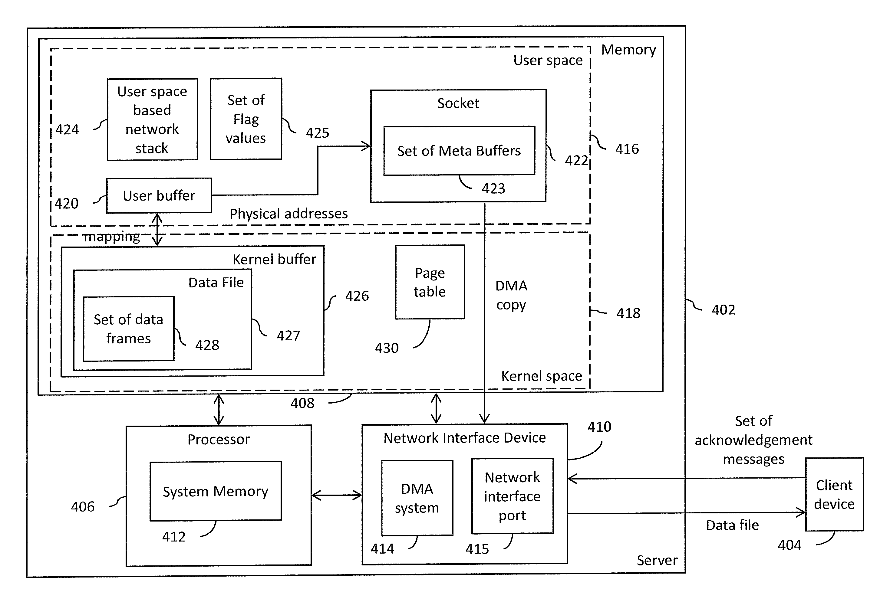
The present invention relates to a data transmission system in a computer network, and more particularly to a data transmission system in a server. The invention provides a method for a server to transmit data files to a client device in a secure and efficient manner. The server uses a virtual address space to protect data files from malicious programs and provides fault tolerance during processing. The server includes a processor, memory, and network interface device that are interconnected with a system bus. The processor identifies the data file, retrieves it from memory, and stores it in the kernel buffer. The processor then transitions from the user mode to the kernel mode to execute read and write system calls to copy the data file to the kernel buffer and transmit it to the client device. The invention allows for efficient and secure data transmission in a computer network.

Problems solved by technology

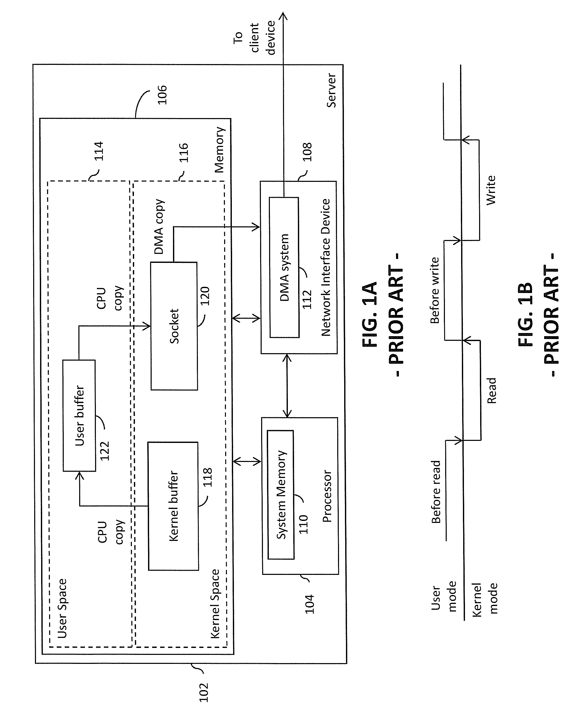
When the server uses a large number of processing cycles for creating data file copies, the number of processing cycles available for user processes is reduced, thereby resulting in reduced performance.
Further, the data file copies consume large spaces in the memory.
Since the server operates on a finite physical memory size, the large spaces occupied by the data file copies cause a reduction in the memory available for other user processes, thus also affecting server performance.
The above-described methods cause the processor to transition between the user and kernel modes multiple times. A large number of processing cycles are wasted by these transitions.
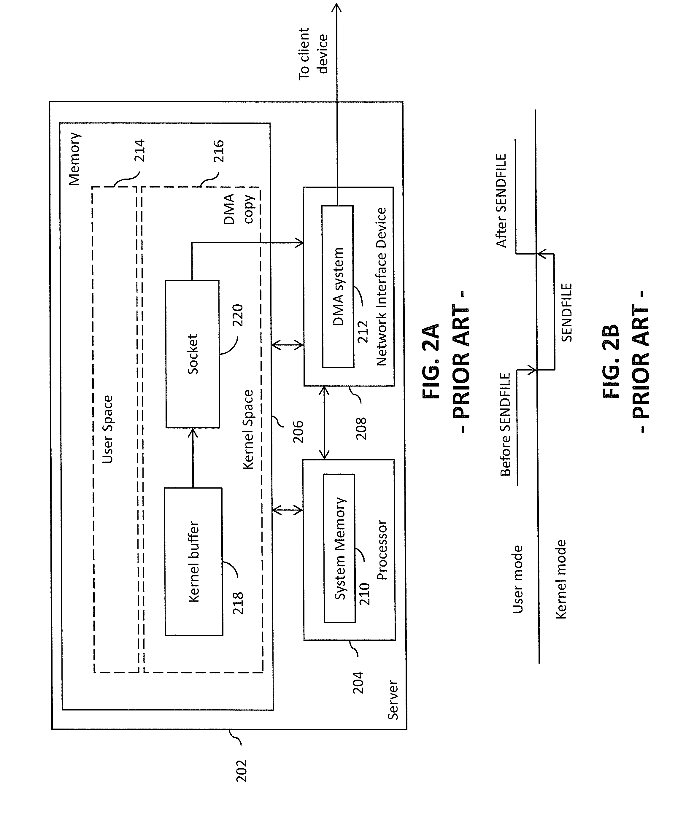
The use of the TLB to execute the SENDFILE system call may result in a TLB miss, which is when a requested virtual address is not present in the TLB.

Method used


Image

  • Zero-copy data transmission system
  • Zero-copy data transmission system
  • Zero-copy data transmission system

Examples


Embodiment Construction

[0030]The detailed description of the appended drawings is intended as a description of the currently preferred embodiments of the present invention, and is not intended to represent the only form in which the present invention may be practiced. It is to be understood that the same or equivalent functions may be accomplished by different embodiments that are intended to be encompassed within the spirit and scope of the present invention.

[0031]In an embodiment of the present invention, a data transmission system is provided. The data transmission system includes a memory, a processor, and a network interface device. The memory includes a plurality of memory locations having corresponding plurality of physical addresses associated therewith. The memory further includes kernel and user spaces. The kernel space stores a plurality of data files and a page table. The page table includes a mapping between a plurality of virtual addresses and corresponding plurality of physical addresses. T...


PUM


Abstract

A data transmission system for transmitting a data file from a server to a client device includes a processor, a memory and a network interface device. The memory includes a user space and a kernel space. The data file is stored in the kernel space. The processor receives a transmission request from the client device for transmitting the data file. The processor maps a set of virtual addresses corresponding to the data file to the user space as a mapped data file, and stores a set of physical addresses corresponding to the set of virtual addresses in a set of meta-buffers of a socket created in the user space. The network interface device retrieves the data file from the kernel space based on the set of physical addresses from the set of meta-buffers, and transmits the data file to the client device.

Description

BACKGROUND OF THE INVENTION[0001]The present invention generally relates to computer networks, and, more particularly, to a data transmission system in a computer network.[0002]A computer network is a group of computing devices interconnected by a transmission medium. The computer network facilitates exchange of information between the computing devices. The computer network includes two types of the computing devices, namely, client devices and servers. Servers contain multiple resources that are shared with other computing devices in the computer network, such as data files that store information that is exchanged between the computing devices. The client devices access the resources provided by the servers.[0003]A server has a memory that stores data files to be transmitted and boot code for booting a server operating system (OS), examples of which include Linux©, Windows©, and Macintosh© OSs. The memory includes multiple physical addresses at which the data files and the boot co...

Claims


Application Information

Patent Timeline
IPC IPC(8): G06F15/167H04L29/06
CPCH04L67/42G06F15/167G06F9/544H04L67/01G06F9/54
Inventor PATHAK, ARUNAGRAWAL, HEMANTMALHOTRA, SAHIL
Owner NXP USA INC
Learn More