
Ultraviolate light sterilization apparatus

a technology of ultraviolet light and sterilization apparatus, which is applied in the direction of medical devices, other medical devices, and diseases, can solve the problems of ineffective internal bacteria, viruses, and protozoa, external microorganisms, and the inability to reproduce, so as to prevent or reduce future infections

Inactive Publication Date: 2016-09-22
DAVIS MATTHEW PHILLIP
View PDF1 Cites 7 Cited by
  • Summary
  • Abstract
  • Description
  • Claims
  • Application Information

AI Technical Summary

Benefits of technology

The invention is a sterilization apparatus that can use UV-C light to sterilize a patient's exhaled breath and the internal pneumatics of anesthesia machines and ventilators. By doing this, the apparatus prevents or reduces future infections that might occur if the machines were not sterilized. The process involves increasing the diameter of the patient circuit and slowing down the velocity of the air to create a 2-10 second time gap for effective sterilization. The device removes larger organisms from the air using bacteria filters. The UV dosage is determined based on a study by Crystal IS, which found a logs reduction of 6 levels to increase sterilization effectiveness. The apparatus includes a power supply and heat sync to provide power and dissipate heat. LED bulbs are needed to achieve the UV dosage, with a minimum of three needed. The internal shroud of the apparatus is reflective to decrease dosage absorption and increase effectiveness.

Problems solved by technology

It is able to penetrate into the cells of these microorganisms and break their DNA strands, essentially disabling their ability to reproduce.
UV sterilization is used in operating rooms currently for the sterilization of external microorganisms, but is ineffective against internal bacteria, viruses, and protozoa.

Method used


Image

  • Ultraviolate light sterilization apparatus
  • Ultraviolate light sterilization apparatus
  • Ultraviolate light sterilization apparatus

Examples


Embodiment Construction

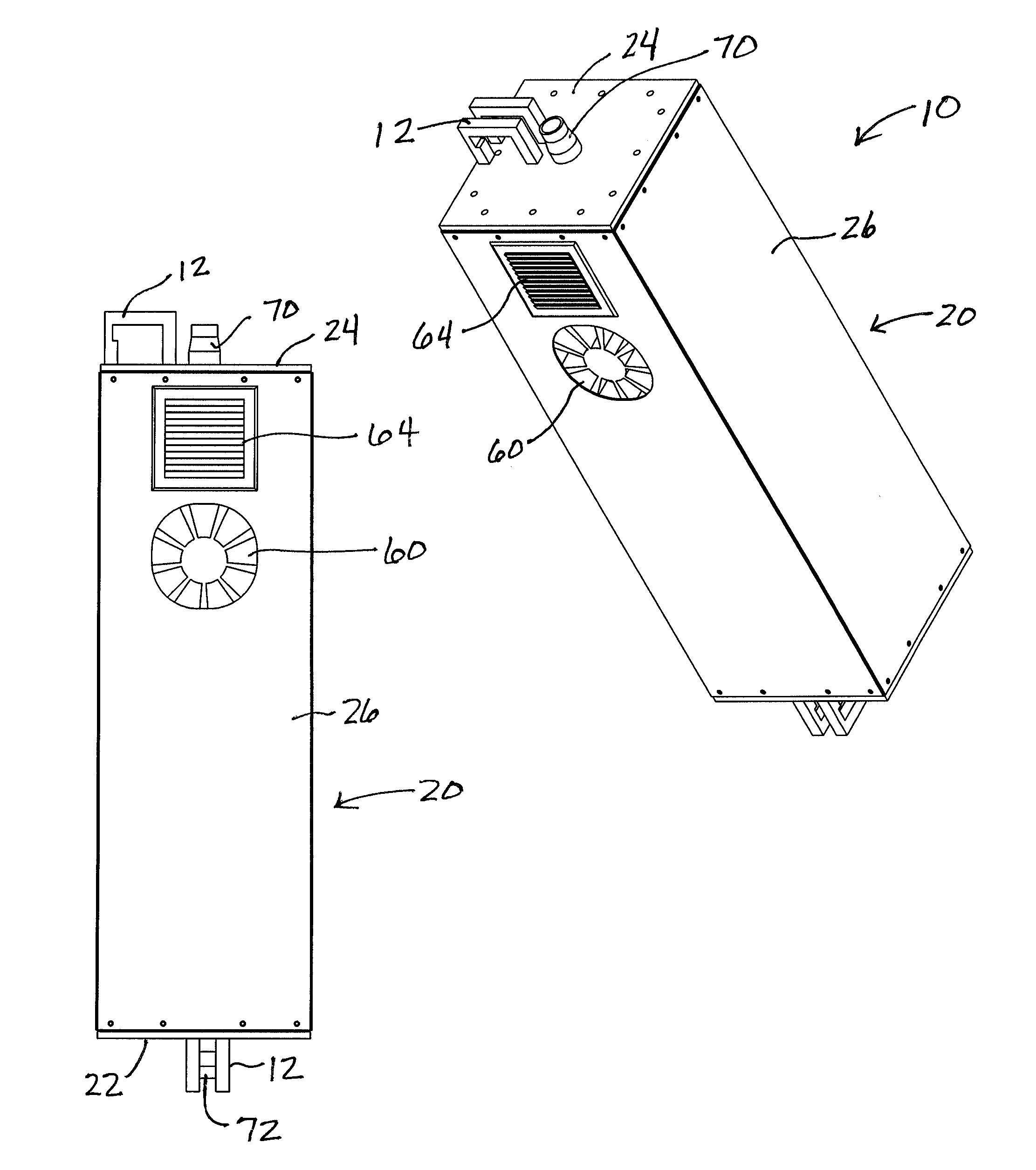
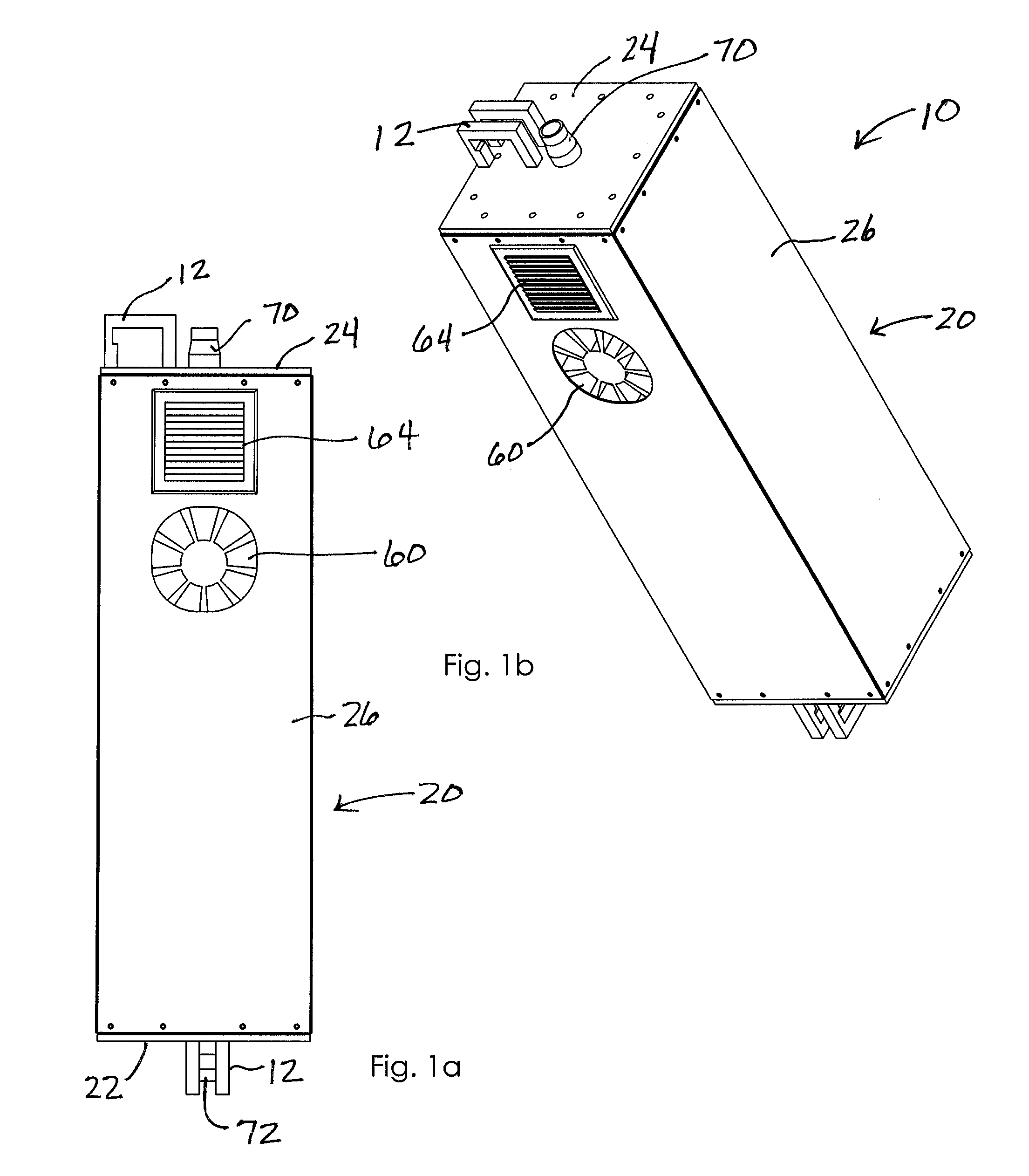
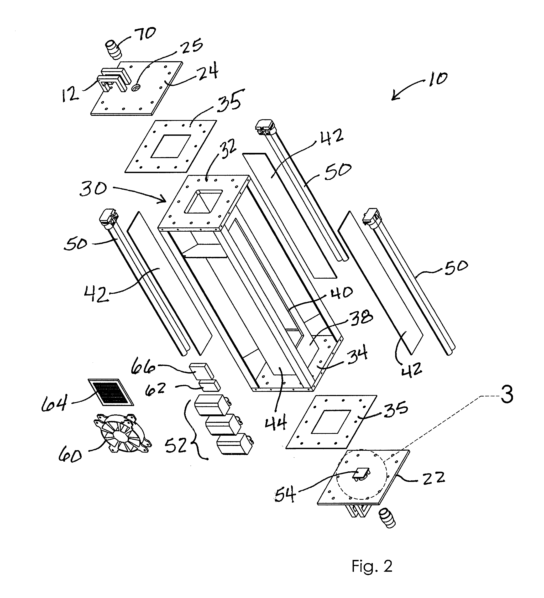
[0040]A sterilization apparatus according to a preferred embodiment of the present invention will now be described in detail with reference to FIGS. 1a to 14 of the accompanying drawings. The sterilization apparatus includes an outer housing 20, an inner housing 30, a plurality of ultraviolet (“UV”) light assemblies 50, and connections to upstream and downstream exhalation airflows to and from a medical patient.

[0041]The outer housing 20 includes a bottom wall 22 and an opposed top wall 24, each having a generally planar configuration. In an embodiment, a plurality of outer housing side walls 26 extends between corresponding peripheral edges of respective bottom and top walls. Together, the side, top, and bottom walls define an interior space, hereafter referred to as an outer chamber 28. The outer housing 20 may be sealed airtight except as otherwise noted below as ambient air will be routed through the outer housing 20. The top wall 24 and the bottom wall 22 of the outer housing 2...


PUM

PropertyMeasurementUnit
diameteraaaaaaaaaa
flow rateaaaaaaaaaa
transparentaaaaaaaaaa

Abstract

A sterilization apparatus for sterilizing air includes an outer housing having side walls extending between opposed bottom and top walls that, together, define an outer chamber. An inner housing is situated in the outer chamber and includes opposed top and bottom ends and having a wall structure that defines a sealed inner chamber extending therebetween. The wall structure includes at least one side wall that defines a transparent window. An inlet port is in communication with one end of the inner chamber and that directs unsterilized air into the inner chamber. An ultraviolet (“UV”) light source is positioned outwardly adjacent the window and configured to emit UV light through the window and into the inner chamber when energized so as to sterilize air in the inner chamber. An outlet port is in communication with another end of the inner chamber that directs sterilized air downstream from the inner chamber.

Description

REFERENCE TO RELATED APPLICATIONS[0001]This application claims the benefit of provisional patent application U.S. Ser. No. 14 / 660,400 filed Mar. 17, 2015 titled LUMENIZATION and which is incorporated completely herein by reference.BACKGROUND OF THE INVENTION[0002]This invention relates generally to sterilization devices and, more particularly, to an apparatus using ultraviolet light for sterilizing a patient's breath.[0003]Hospital acquired infections, also known as nosocomial infections, are considered a top five cause of death according to the CDC, with as many as 1.7 million acquired infections every year. Anesthesia machines and ventilators are considered life-support equipment since they provide artificial breathing to individuals. Due to the cycle of air, and repeated processes on a multitude of individuals, each machine will begin to accumulate bacteria in the internal pneumatics. This bacteria, which is trapped is a potential cause for nosocomial infection, since many patien...

Claims


Application Information

Patent Timeline
Patent Type & Authority Applications(United States)
IPC IPC(8): A61L9/20A61M16/00A61M16/01
CPCA61L9/20A61M16/0057A61M16/01A61M16/0875A61M16/1055A61M2205/3368A61M2209/10A61M16/1065A61M16/107A61L2209/16
Inventor DAVIS, MATTHEW PHILLIP
Owner DAVIS MATTHEW PHILLIP
Learn More