Damping strut with a hydraulic shock absorber and method for operating the damping strut

a technology of hydraulic shock absorber and damping strut, which is applied in the direction of vibration dampers, springs/dampers, functional characteristics, etc., can solve the problem of becoming a safety risk for the rider

Active Publication Date: 2016-09-15
RIPA THOMAS
View PDF5 Cites 3 Cited by
  • Summary
  • Abstract
  • Description
  • Claims
  • Application Information

AI Technical Summary

Benefits of technology

[0041]Furthermore, according to an aspect of the invention the biasing means is an electromagnet and the bias regulator is an electric current control circuit, via which the strength of the magnetic field generated by the electromagnet can be controlled, and via which the electromagnet interacts with the valve disk for generating the bias. According to another aspect of t

Problems solved by technology

The flow of the damping fluid in the monotube shock absorber, in particular through the damping openings, is lossy, and results in a damping strut resistance force that counteracts the movement of the damping strut.
Pedalling ind

Method used


Image

  • Damping strut with a hydraulic shock absorber and method for operating the damping strut
  • Damping strut with a hydraulic shock absorber and method for operating the damping strut
  • Damping strut with a hydraulic shock absorber and method for operating the damping strut

Examples


Embodiment Construction

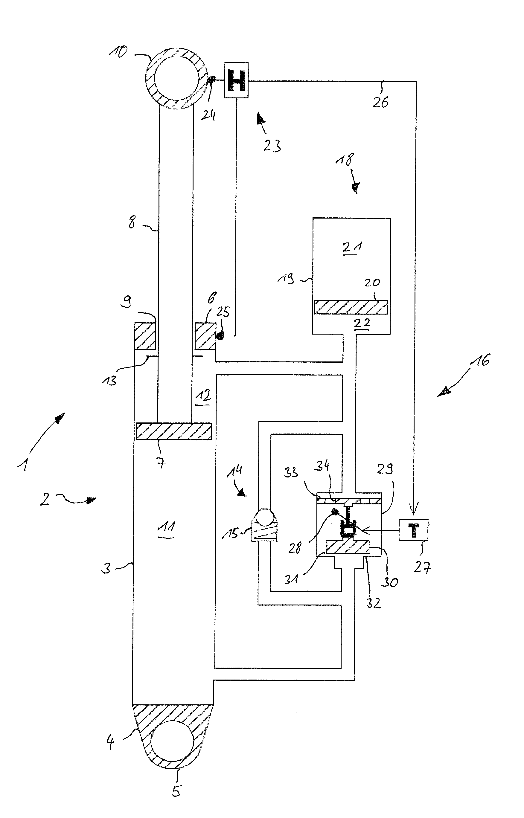
[0055]FIG. 1 shows a damping strut 1 that includes a shock absorber 2. The shock absorber 2 has a damping cylinder 3 that includes a damping cylinder head 4, seen in FIG. 1 on its lower side, wherein a wheel eye 5 is formed on the damping cylinder head 4. The wheel eye 5 is provided for receiving a wheel, wherein the wheel suspension of the wheel is provided by the damping strut 1. Further, the damping cylinder 3 includes on a side facing away from the damping cylinder head 4 a damping cylinder floor 6, wherein a volume is formed between the damping cylinder head 4 and the damping cylinder floor 6, wherein the volume is filled with an incompressible damping fluid, for example oil. A damping piston 7 with a damping piston rod 8 is arranged in the volume such that it can be longitudinally displaced, wherein the damping piston rod 8 is guided through an opening 9 in the damping cylinder floor 6. A frame eye 10 is formed on the outer longitudinal end of the damping piston rod 8, wherein...


PUM


Abstract

A damping strut with a hydraulic shock absorber has a damping volume filled with an incompressible damping fluid, a retract detection device, and a compression stage throttle having a disk valve with a valve disk. The damping fluid flows through the compression stage throttle during a retraction of the shock absorber and generates a damping strut resistance force. A biasing means for biasing the valve disk against a through flow direction of the disk valve has a force-distance-characteristic curve in a range of the valve stroke of the valve disk, a first derivative of which is substantially zero and has a value (K). A bias regulator couples the biasing means with the valve disk and is interconnected with the retract detection device. When the retraction of the shock absorber starts, the value (K) is raised during a first period of time starting at a single start value.

Description

CROSS REFERENCE TO RELATED APPLICATIONS[0001]This application is a continuation application of international patent application PCT / EP2014 / 074859, filed Nov. 18, 2014, designating the United States and claiming priority from German application 10 2013 112 734.7, filed Nov. 19, 2013, and the entire content of both applications is incorporated herein by reference.FIELD OF THE INVENTION[0002]The invention relates to a damping strut with a hydraulic shock absorber and a method for operating the damping strut.BACKGROUND OF THE INVENTION[0003]A damping strut in combination with a spring strut utilized as a wheel suspension for a bicycle is known. The damping strut has a hydraulic shock absorber that is a monotube shock absorber filled with a damping fluid. A damping piston is supported in the monotube shock absorber such that it can be displaced longitudinally for displacing the damping fluid. The damping piston has a plurality of damping openings. During retraction and extension of the d...

Claims


Application Information

Patent Timeline
IPC IPC(8): F16F9/512F16F9/348
CPCF16F9/512F16F9/3488F16F2238/04F16F2228/066F16F9/19F16F9/464
Inventor RIPA, THOMAS
Owner RIPA THOMAS
Why Eureka
Try Eureka