Reduction in stress cracking of films
a film and stress cracking technology, applied in the field of film stress cracking reduction, can solve the problems of film sticks, not being able to move to relieve stress, etc., and achieve the effect of reducing or substantially reducing the stress cracking of polymers and lowering the surface energy of packaging materials
- Summary
- Abstract
- Description
- Claims
- Application Information
AI Technical Summary
Benefits of technology
Problems solved by technology
Method used
Image
Examples
example 1
Comparative Testing Between Two Materials
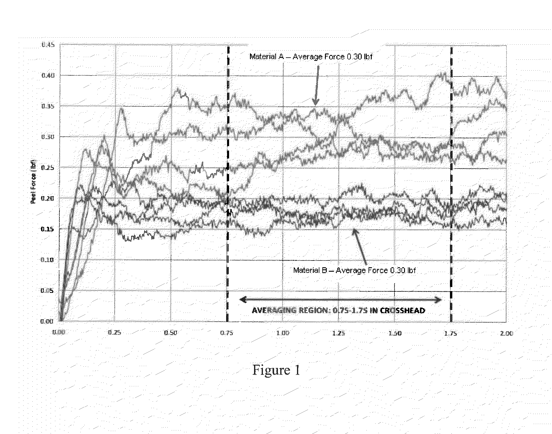
[0098]Two materials were tested for peel force using a load frame and packaging tape. The first material (“Material A”) was a packaging product having a surface made from ethylene acrylic acid, and the second material (“Material B”) was a packaging product having a surface made from LDPE. FIG. 1 demonstrates the foil film peel test results for these two materials.
[0099]Test samples were one inch wide. The ends of the tape and the substrate films were clamped by grips of an MTS load frame. The tests were run at 2 inches per minute speed. The load rises as the specimen ends are pulled until the sample is taught and peeling progresses. Once peeling is initiated, the load is variable based on the local bond strength between packaging tape and the substrate film. The data became more stable after a moderate opening length, and the test data was averaged over on opening distance of 0.75 inches to 1.75 inches.
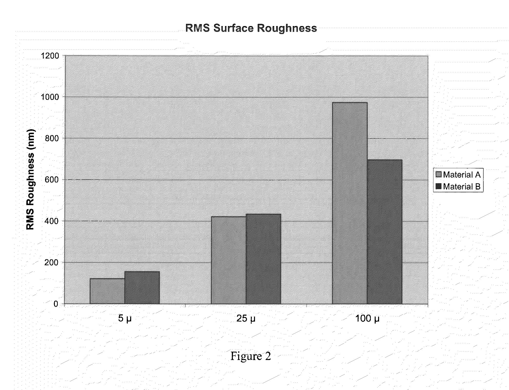
[0100]Water contact angle tests were the...
example 2
Comparative Testing
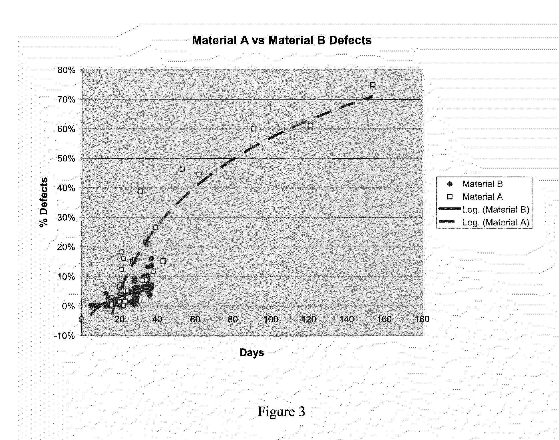
[0105]Two lots of film product, both including PEO as a polymeric component, were manufactured and packaged in two separate packaging materials. The first packaging material included an inner surface made from ethylene acrylic acid and the second packaging material included an inner surface made from LDPE. These lots were inspected after 20 weeks for stress cracked strips.
[0106]After twenty weeks, the first lot packaged in the ethylene acrylic acid packaging showed 30.4% stress cracking, and the first lot packaged in the LDPE packaging showed 4.2% stress cracking. Also after twenty weeks, the second lot packaged in the ethylene acrylic acid packaging showed 46.4% stress cracking, and the first lot packaged in the LDPE packaging showed 0% stress cracking.
example 3
Use of LDPE Packaging Material
[0107]Five lots of film material, each including PEO as a polymeric component, were packaged in a packaging material including an inner surface made from LDPE and placed in a 36 month stability program. The samples were stored at either 25° C. or 30° C. At the end of the 36 months, samples were inspected for stress cracking. The results are presented in Table 2 below:
TABLE 2Stress cracking after 36 months storage at different temperature conditions.StoragePercentageNumber oftemperaturewith StressLot No.Samples(° C.)Cracking125250%225250%325250%425250%525250%125300%225300%325300%425300%525300%
PUM
| Property | Measurement | Unit |
|---|---|---|
| distance | aaaaa | aaaaa |
| distance | aaaaa | aaaaa |
| peel force testing | aaaaa | aaaaa |
Abstract
Description
Claims
Application Information
 - R&D
- Intellectual Property
- Life Sciences
- Materials
- Tech Scout
- Unparalleled Data Quality
- Higher Quality Content
- 60% Fewer Hallucinations
Browse by: Latest US Patents, China's latest patents, Technical Efficacy Thesaurus, Application Domain, Technology Topic, Popular Technical Reports.
© 2025 PatSnap. All rights reserved.Legal|Privacy policy|Modern Slavery Act Transparency Statement|Sitemap|About US| Contact US: help@patsnap.com


