
Self-Localization Device and Movable Body

a self-localization and movable body technology, applied in image analysis, image enhancement, instruments, etc., can solve the problems of reducing map matching accuracy, affecting so as to inhibit an increase in processing load and improve the accuracy of self-localization

Active Publication Date: 2016-09-01
HITACHI LTD
View PDF3 Cites 26 Cited by
  • Summary
  • Abstract
  • Description
  • Claims
  • Application Information

AI Technical Summary

Benefits of technology

The patent aims to improve the accuracy of self-localization in a device without relying on satellite positioning. It does this by recovering from a state where the device has lost its self-location while keeping processing loads low. This improves the accuracy of self-localization in a device mounted with a camera, such as a vehicle-mounted camera.

Problems solved by technology

However, techniques using dead reckoning or map matching and satellite positioning do riot guarantee accuracy of self-localization and thus, even if these techniques are used complexly, the accuracy if self-localization is not improved.
Therefore, the loss of self-location due to an increased error of the estimated self-location occurs frequently.
That is, in a conventional device using dead reckoning and map matching complexly in a time sequence as typically described in JP-2008-165275-A, an estimation error of the self-location in the past is reflected in a current self-localization result and thus, with an increasing moving amount, the accuracy of map matching decreases and the self-location may sooner or later be lost.
Satellite positioning such as GPS can be used outdoors, but depending on the weather or the time zone, the precision is degraded or a positioning signal cannot be received and thus, the position cannot be determined, which makes satellite positioning unsuitable as an alternative when the self-location is lost.
However, with an increasing scan range of the map for map matching, matching objects of the map increase and thus, unless the matching object is an explicit marker, the accuracy of map matching does not improve and therefore, the accuracy of self-localization does not improve.
As described above, improving the accuracy of self-localization. without depending on satellite positioning whose precision easily changes depending on the weather or the time zone in any traveling environment where there is no explicit marker is present has become a challenge.

Method used


Image

  • Self-Localization Device and Movable Body
  • Self-Localization Device and Movable Body
  • Self-Localization Device and Movable Body

Examples


example 1

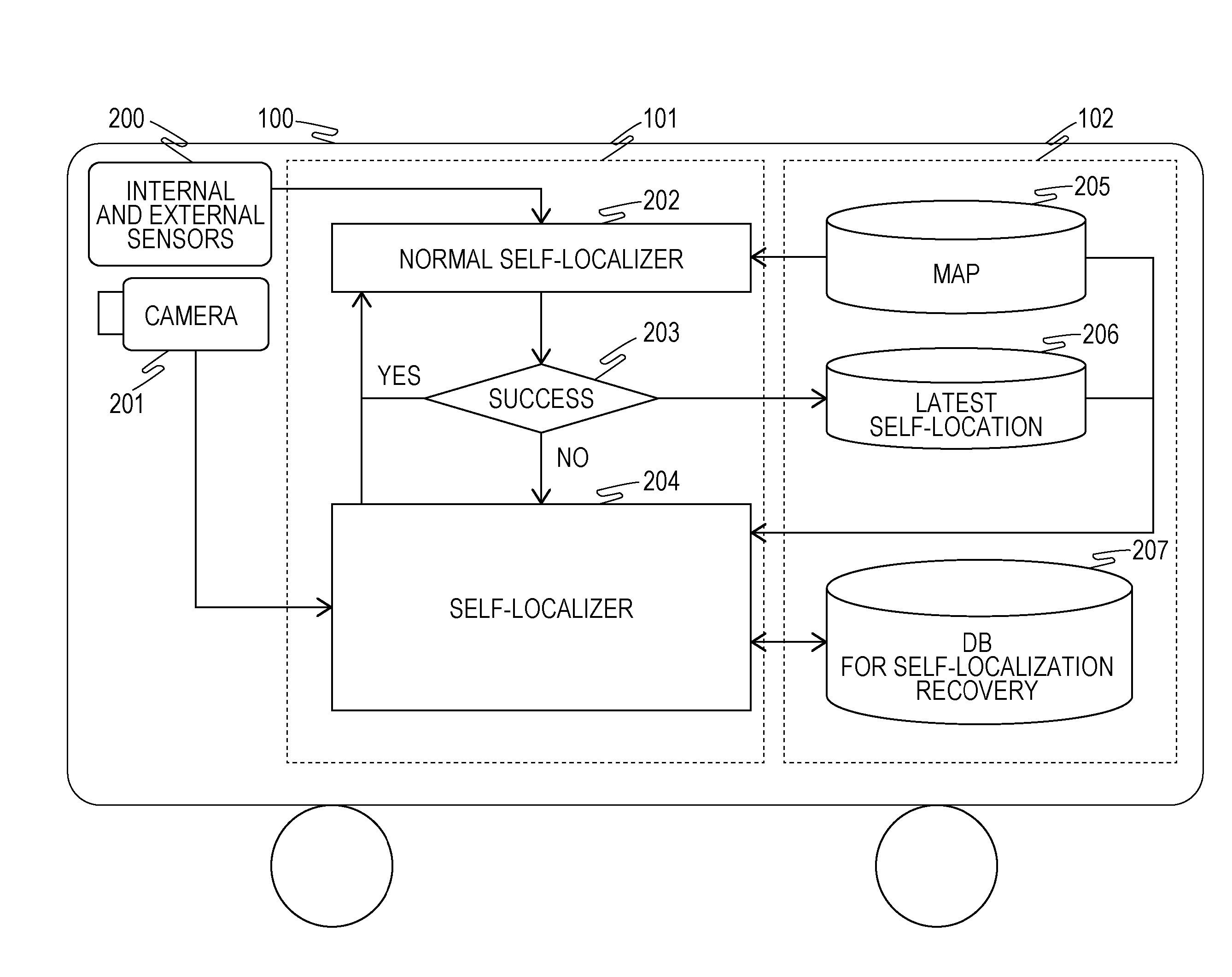
[0024]In the present example, a movable body such as a vehicle or a robot that self-localizes is mounted with a camera and when the self-location is lost, recovers from a state in which the self-location is lost by a self-localization device according to the present invention.

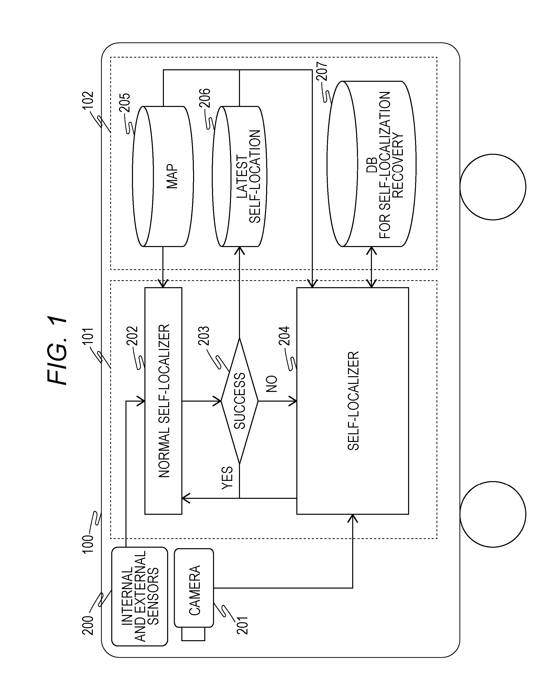
[0025]FIG. 1 shows the configuration of a movable body 100 according to the present example and the movable body 100 is mounted with an internal and external sensor 200 and a camera 201 used by a self-localization device according to the present invention and further, a CPU 101 and a storage device 102. In FIG. 1, a normal self-localizer 202 and a self-localizer 204 as programs executed by the CPU 101 are shown as a function block diagram.

[0026]The internal and external sensor 200 is a sensor needed for a self-localization technique performed by the normal self-localizer 202 described below such as a rotary encoder, a gyro sensor, and an inertial measurement unit (IMU) to perform dead reckoning, a laser distanc...


PUM


Abstract

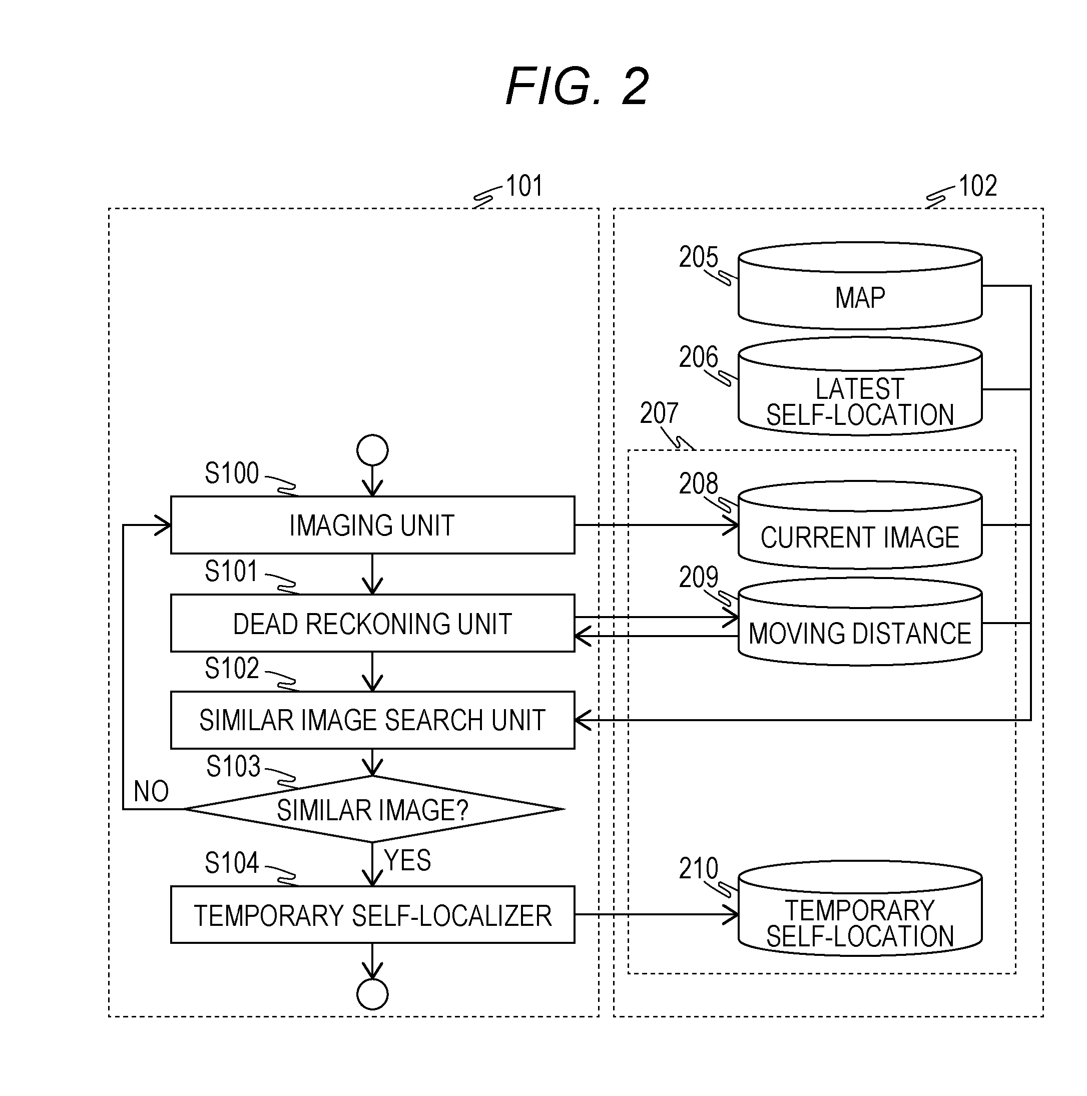
A self-localization device including a storage unit that associates and stores a plurality of reference images and imaging positions of the plurality of respective reference images and an operation unit that periodically estimates a self-location of a movable body based on information obtained from a sensor included in the movable body, wherein the operation unit determines, when estimation of the self-location fails, a moving distance from a latest self-location obtained from successful estimation of the self-location before the estimation fails using the information from the sensor and extracts a plurality of the reference images belonging to a range of the moving distance from the latest self-location and searches the plurality of extracted reference images for images similar to a current image captured by an imaging device included in the movable body to estimate the self-location of the movable body.

Description

BACKGROUND OF THE INVENTION[0001]1. Field of the Invention[0002]The present invention relates to a self-localization technology when a movable body mounted with a camera self-localizes.[0003]2. Description of the Related Art[0004]Various devices that estimate a self-location of a movable body based on information acquired from sensors including internal sensors such as a rotary encoder and a gyro sensor and external sensors such as a camera and a laser distance sensor mounted on the movable body such as a robot or a vehicle have been proposed. A technique to estimate a relative self-location from a reference point by adding up moving amounts of a movable body acquired by an internal sensor such as a rotary encoder or a gyro sensor is called dead reckoning and is superior in real-time properties due to its low-load calculation processing, but a position error accumulates in accordance with the moving amount. On the other hand, a technique to estimate a self-location based. on, after ...

Claims


Application Information

Patent Timeline
IPC IPC(8): G06T7/00
CPCG06T7/0044G06T2207/30244G06T7/0026G06T7/74G06T2207/30252
Inventor IIMURA, TAIKI
Owner HITACHI LTD
Learn More