High efficiency hydronic circulator with sensors

a high-efficiency, hydronic circulator technology, applied in the direction of positive displacement liquid engine, magnetic circuit rotating parts, magnetic circuit shape/form/construction, etc., can solve the problem of motors that were noisier than desirable for residential use, and achieve greater output and efficiency, reduce noise, and greatly increase the effect of magnetic flux

Inactive Publication Date: 2016-08-11
TACO
View PDF5 Cites 10 Cited by
  • Summary
  • Abstract
  • Description
  • Claims
  • Application Information

AI Technical Summary

Benefits of technology

This patent describes a highly efficient, standalone circulator system for a hydronic heating or cooling system. It is controlled by at least one thermal sensor placed in the flow conduits of the hydronic system, providing data for the pump controller to determine the optimal output flow of the pump under specific temperature differential conditions. The system uses a ferrite permanent magnet rotor and a system of stator coils powered by a non-stepped down, sinusoidally varying DC voltage from a rectified AC power supply. The VFD system smoothly reacts to changes in system loads, minimizing noise and power loss. Additionally, the flux from the standard ceramic ferrite magnet can be increased by orienting it to form an anisotropic ferrite magnet. The advantages of the ferrite magnet include inertness to the wet environment and maintaining magnetic quality at higher temperatures.

Problems solved by technology

The use of the rare earth rotor magnet and the use of relatively low input voltage of 12 volts DC, resulted in a motor which, although relatively highly efficient, was costly, utilized a trapezoidal control strategy, and resulted in a motor that was noisier than desirable for residential use.

Method used


Image

  • High efficiency hydronic circulator with sensors
  • High efficiency hydronic circulator with sensors
  • High efficiency hydronic circulator with sensors

Examples


Embodiment Construction

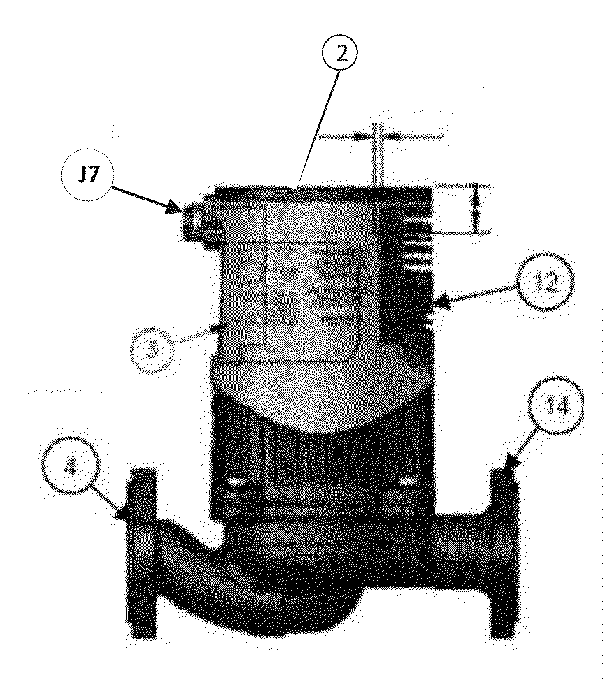
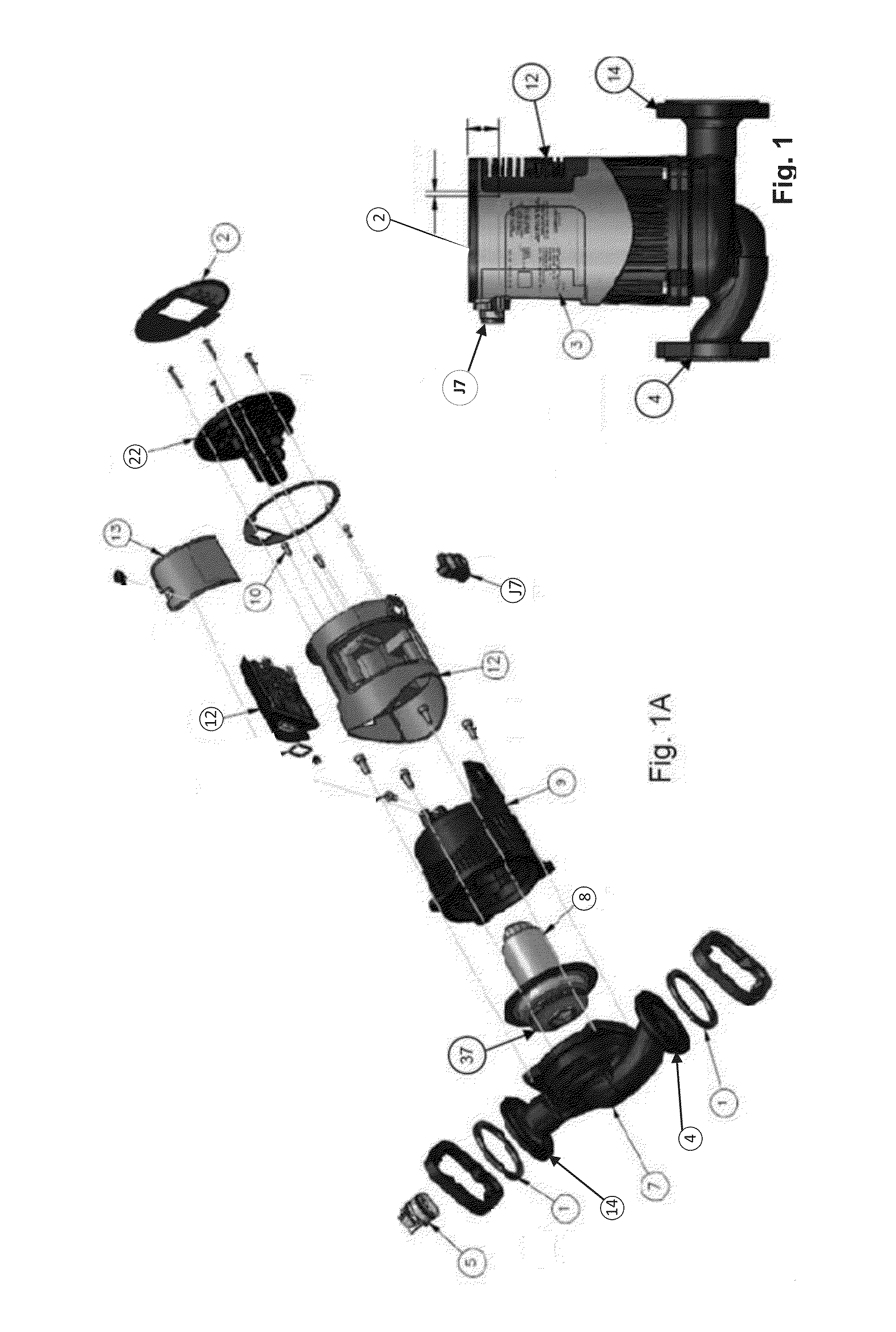
[0044]Referring to the drawings, the circulator includes an impeller 37, which is directly connected to a permanent magnet rotor 8 in the pump motor. The impeller 37 is held within the impeller chamber 7 and moves the fluid between the fluid inlet 4 and the fluid outlet (see fig IA). The motor is controlled by the Central Processing Unit (the “CPU”) and Digital Signal Processor (“DSP”), on the printed circuit board (“PCB”) of the motor control board, generally indicated by the numeral 116, which is directly connected to the stator windings within the housing 9. A diagram of the motor control PCB 116 circuitry is shown in FIG. 8a. The details of the sensor and power control PCB are depicted in FIGS. 9, 9A, 9B, and is generally shown by the numeral 22 in FIG. 1A

[0045]The high voltage power is passed from the power control PCB 22 via the connectors TP6, TP7, to the motor control PCB 116 through the two-pin header J6.

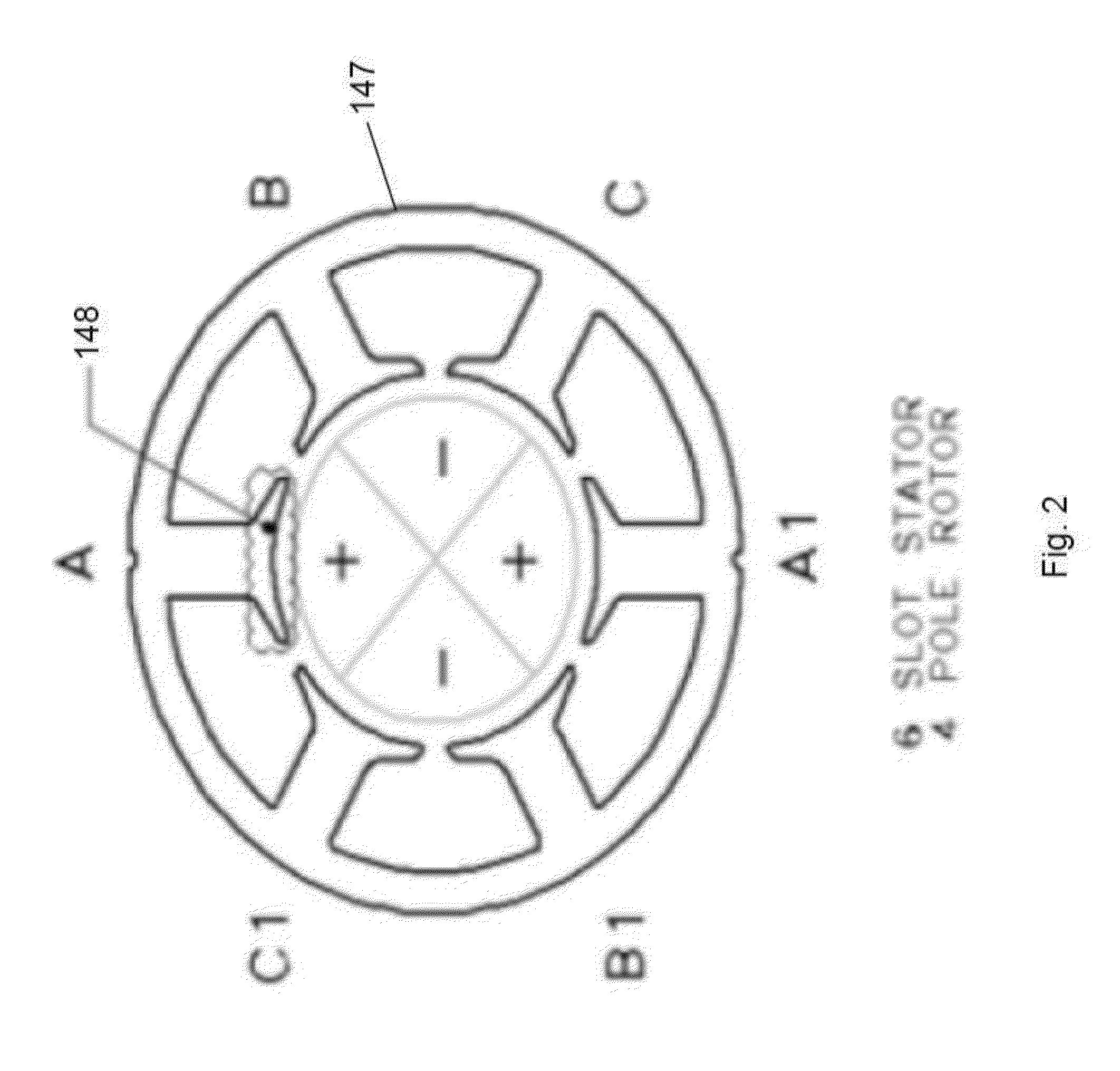
[0046]The details of the stator are shown more fully in FIGS. 2 and 3,...


PUM


Abstract

A highly efficient circulator system is provided, useful for hydronic systems, including both heating and cooling systems. The stand-alone circulator motor is controllable by input from certain sensors, preferably thermal sensors, which provide data enabling the controller of the brushless pump motor to vary its flow output to meet changes in systems loads. The circulator has a ceramic permanent magnet rotor, such as a ferrite, with an electronically, preferably sinusoidally, commutated, electro-magnetic stator controlling the input of electrical power.

Description

[0001]This application claims the benefit of priority pursuant to 35 U.S.C. 119(e) from a U.S. Provisional Patent Application No. 62 / 115,050 filed on Feb. 11, 2015, the text of which is fully incorporated by reference herein as if repeated below.[0002]The present invention is directed to a highly efficient circulator system, useful for hydronic systems, including both heating and cooling systems. Specifically, this stand-alone circulator is controllable by input from certain sensors, preferably thermal sensors, which provide data enabling the controller of the brushless pump motor to vary its flow output to meet changes in systems loads. The circulator has a molded, ceramic, such as a ferrite, permanent magnet rotor with an electronically, preferably sinusoidally commutated, electro-magnetic stator controlling the input of electrical power.BACKGROUND OF THE INVENTION[0003]It has previously been well known to provide a thermal sensor-controlled, electronically commutated, permanent m...

Claims


Application Information

Patent Timeline
Patent Type & Authority Applications(United States)
IPC IPC(8): F04D15/00F04D13/06H02K11/04F04D1/00H02K1/27H02K11/00
CPCF04D15/0066H02K1/27F04D13/06H02K11/044F04D1/00H02K11/0073H02K11/33H02K11/05F04D13/064F04D13/0686Y02B30/70F04B49/065
Inventor THOMPSON, STEVESTAKEV, VLADISLAV MICHEVBIRKENSTOCK, JR., ROBERT F.BIRD, DOUGLASSWEET, DAVID E.
Owner TACO
Why Eureka
Try Eureka