
Thermal spraying apparatus and thermal spraying method

a technology of thermal spraying apparatus and thermal spraying method, which is applied in the direction of mechanical apparatus, machines/engines, coatings, etc., can solve the problems of unsatisfactory productivity and inability to prevent the adhesion of thermal spray droplets, and achieve the effect of effectively preventing thermal spray droplets

Inactive Publication Date: 2016-08-11
TOYOTA JIDOSHA KK
View PDF0 Cites 3 Cited by
  • Summary
  • Abstract
  • Description
  • Claims
  • Application Information

AI Technical Summary

Benefits of technology

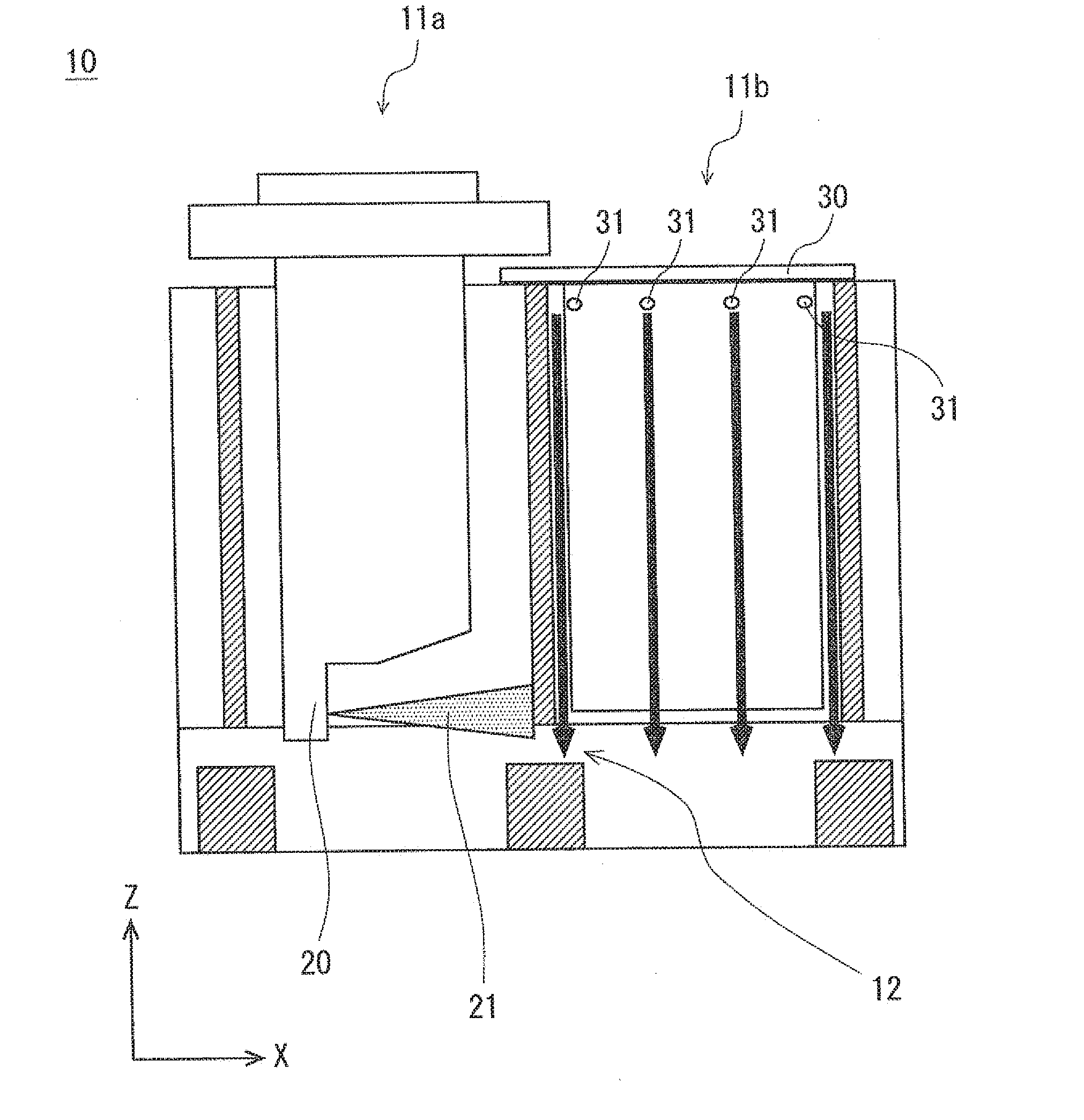
The present patent is about a thermal spraying apparatus that includes a gun to spray material onto the inner wall of a cylinder block. A gas blowing jig is inserted into an adjacent cylinder bore to prevent the thermal spray droplets from adhering to it. Blowing openings in the jig allow gas to flow downward and prevents the material from accumulating on the jig. The blowing openings can be arranged to improve the gas flow. The technical effect is that the apparatus prevents the material from accumulating on the adjacent cylinder bore and improves the quality of the thermal spray coating.

Problems solved by technology

However, it would still be impossible to prevent thermal spray droplets from adhering to apart of the jig that is opposed to the breathing hole.
Therefore, it is necessary to remove the thermal spray droplets adhered to the jig each time the thermal spraying task is finished before starting the next task, leading to unsatisfactory productivity.

Method used


Image

  • Thermal spraying apparatus and thermal spraying method
  • Thermal spraying apparatus and thermal spraying method
  • Thermal spraying apparatus and thermal spraying method

Examples


modified examples

[0052]Modified examples of the gas blowing jig 30 are explained with reference to FIGS. 8 to 10. FIGS. 8 to 10 show modified examples of the arrangement of blowing openings 31. FIGS. 8 to 10 schematically show the structures of gas blowing jigs 30. Note that the structure of the gas blowing jig 30 except for the arrangement of the blowing openings 31 is similar to that of the first exemplary embodiment, and therefore its explanation is omitted as appropriate.

[0053]FIG. 8 is a side view schematically showing a gas blowing jig 30 according to a modified example 1. In FIG. 8, a blowing opening 31 has a slit shape. That is, the blowing opening 31 has its longitudinal direction perpendicular to the Z-direction and is formed along the outer circumferential surface. Even with this structure, a gas is blown downwardly from the top of the adjacent cylinder bore 11 throughout the entire inner wall surface thereof. Even in the structure shown in FIG. 8, a plurality of slit-shaped blowing openi...


PUM

PropertyMeasurementUnit
structureaaaaaaaaaa
internal structureaaaaaaaaaa
structuresaaaaaaaaaa

Abstract

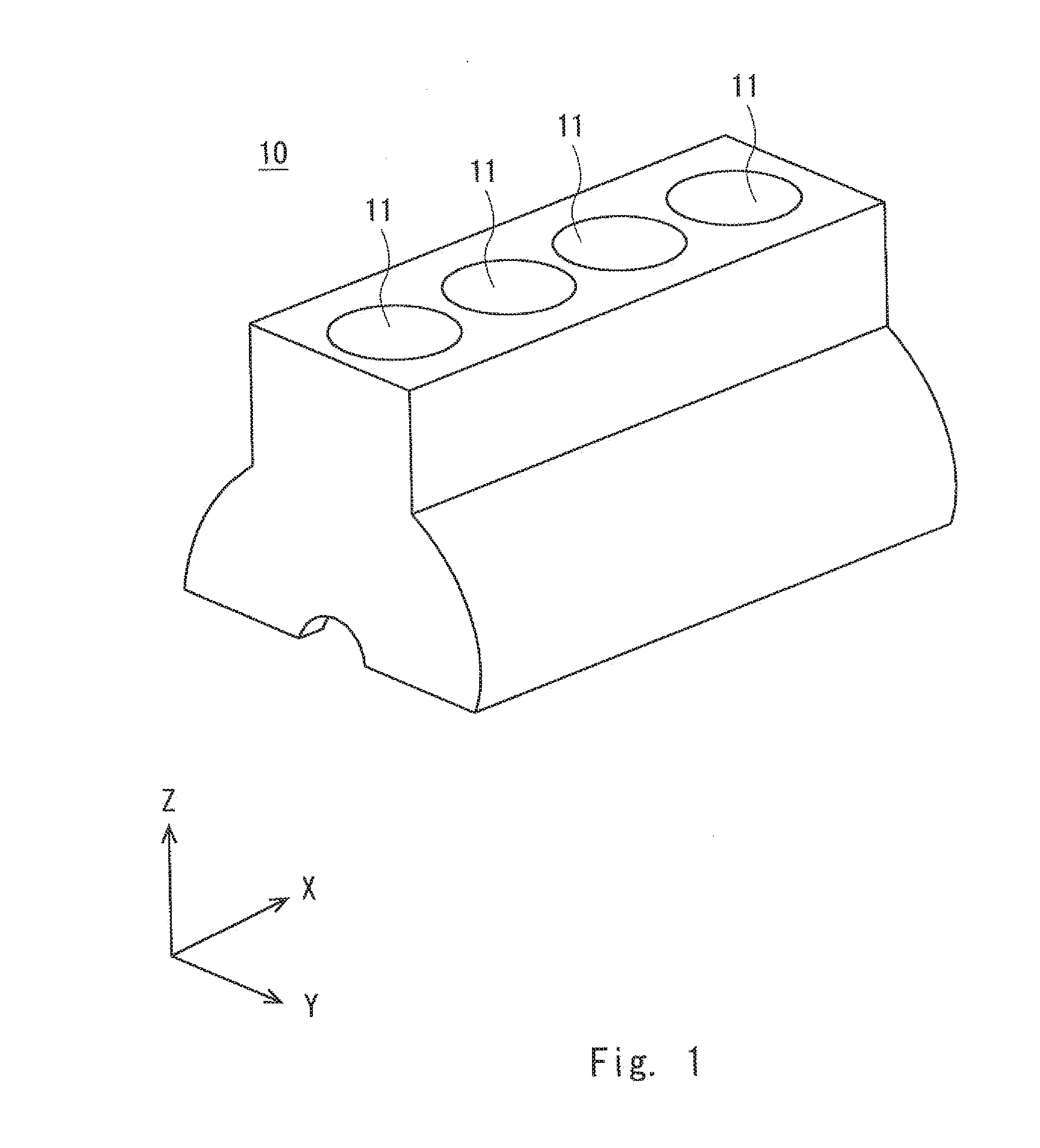
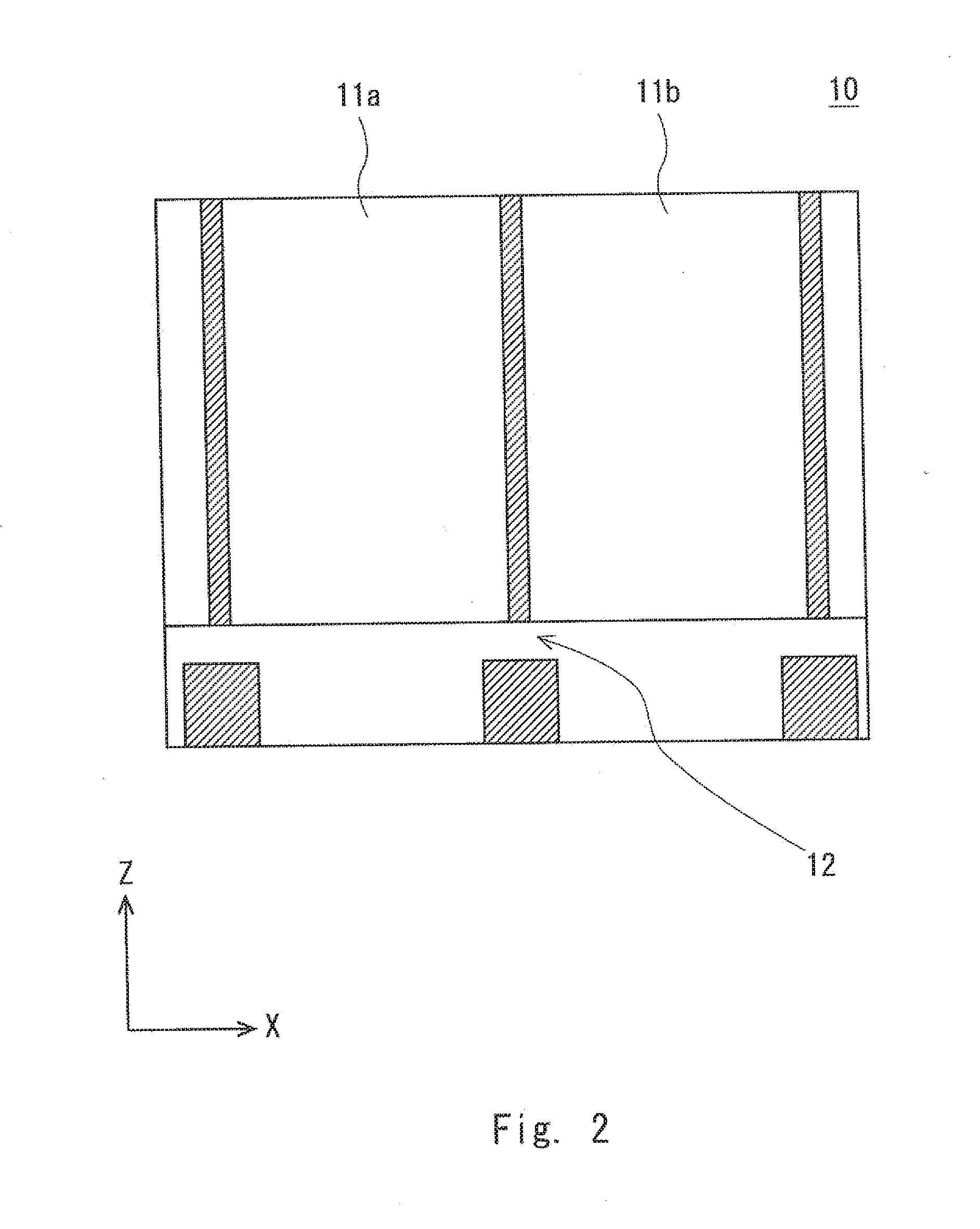
A thermal spraying apparatus and a thermal spraying method capable of preventing thermal spray droplets from adhering to a cylinder bore. A thermal spraying apparatus according to an exemplary embodiment includes a thermal spraying gun that sprays a thermal spray material on an internal wall surface of a cylinder bore of a cylinder block, and a gas blowing jig inserted into the inside of an adjacent cylinder bore adjacent to the cylinder bore, blowing openings being formed in the gas blowing jig, the blowing openings being configured so that a gas is blown therefrom and flows downward from the top of the adjacent cylinder bore throughout the entire inner wall surface thereof.

Description

INCORPORATION BY REFERENCE[0001]This application is based upon and claims the benefit of priority from Japanese patent application No. 2015-22284, filed on Feb. 6, 2015, the disclosure of which is incorporated herein in its entirety by reference.BACKGROUND OF THE DISCLOSURE[0002]1. Field of the Disclosure[0003]The present disclosure related to a thermal spraying apparatus and a thermal spraying method.[0004]2. Description of Related Art[0005]Japanese Unexamined Patent Application Publication No. 2006-233960 discloses a thermal spraying masking method for a cylinder block for a V-engine. In the method disclosed in Japanese Unexamined Patent Application Publication No. 2006-233960, a thermal spraying gun is inserted in a cylinder bore in one of the cylinder banks and an air curtain gun is inserted in a cylinder bore in the other cylinder bank. Further, the air curtain gun blows air during the thermal spraying process performed by the thermal spraying gun. This prevents any of the ther...

Claims


Application Information

Patent Timeline
Patent Type & Authority Applications(United States)
IPC IPC(8): F02F7/00F02F1/00B05B15/04C23C4/00B05B7/16C23C4/12C23C4/131
CPCB05B13/0636B05B15/0431F02F7/0095C23C4/00F02F1/004B05B7/16C23C4/06C23C4/12B05B12/18
Inventor HIRANO, TAKUZOTATSUMI, ATSUYOSHITAKEUCHI, YUSHI
Owner TOYOTA JIDOSHA KK
Learn More