
Surgical Drill Bit

a drill bit and surgical technology, applied in the field of surgical drill bits, can solve the problems of drill bit failure inside the bone, increased temperature, and surgeons' bone problems, and achieve the effect of less subject to wandering, minimizing deficiencies, and reducing the number of subjects

Inactive Publication Date: 2016-08-11
CUTTING EDGE MEDICAL LLC
View PDF1 Cites 15 Cited by
  • Summary
  • Abstract
  • Description
  • Claims
  • Application Information

AI Technical Summary

Benefits of technology

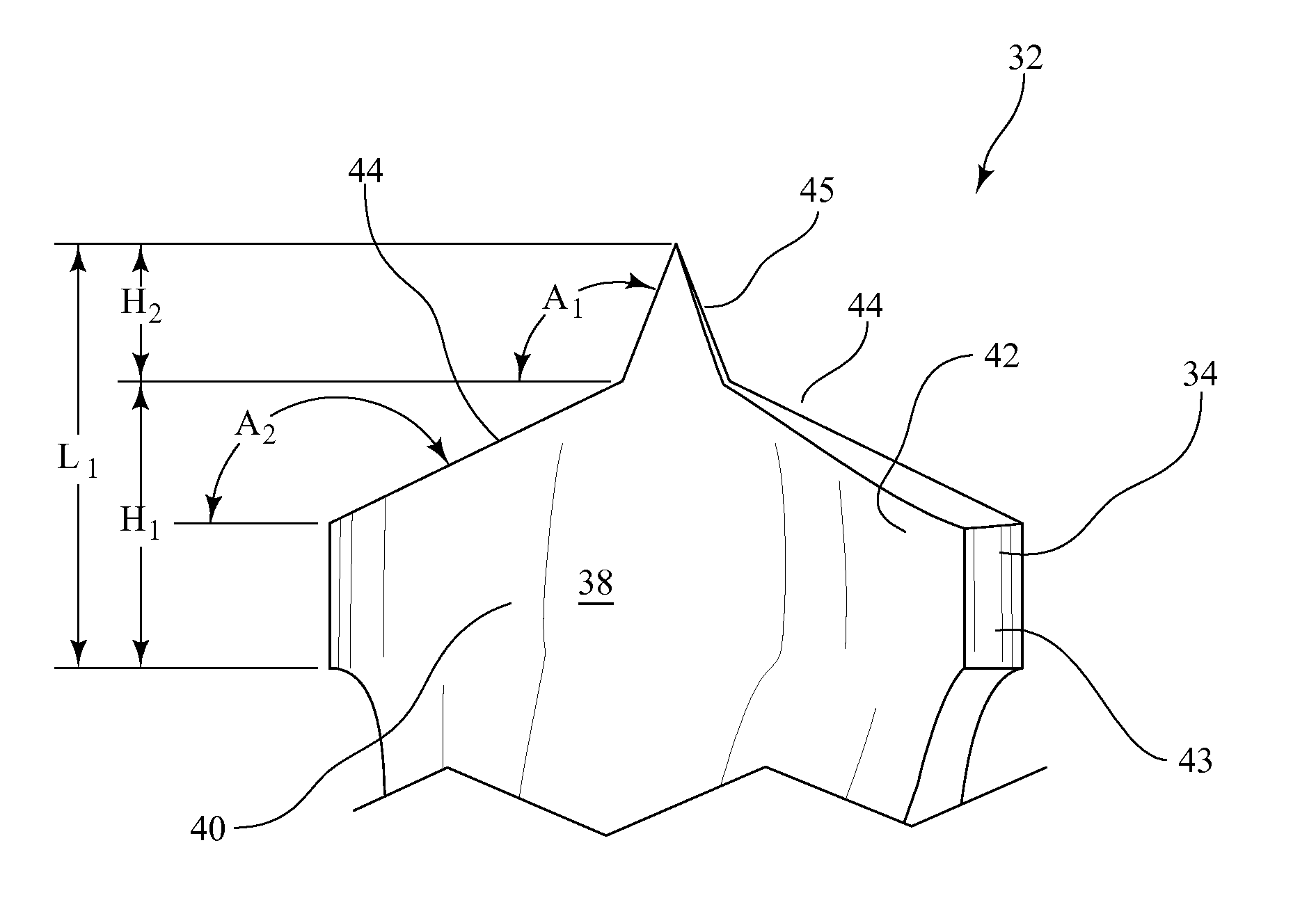
The present invention relates to a surgical drill bit that is designed to minimize the heat buildup and deficiencies that were present with previous surgical drill bits. The drill bit of the present invention has improved resistance to torsional and flexural stress, which means it is less likely to fail during a drilling procedure. The drill bit has a distal end with one or more flutes that form lands along the length of the drill section and a drill point with at least two opposed cutting edges. The angle between the cutting edges is between 90° and 180° and the diameter of the drill section is held at a minimum for minimum bearing surface area to reduce contact between the surface and the wall of the bore being formed. The drill bit also has a centric starter tip to aid in maintaining the position of the drill bit upon startup.

Problems solved by technology

The drilling of bone presents several problems for the surgeon.
The chief problem being an increase in temperature caused by friction during the drilling process.
Other risks include drill bit failure inside the bone that sometimes must be left in the bone because it cannot be extracted.
Yet another problem is so called “bit walking” that is difficulty in holding the drill bit at the desired location, especially when drilling into bone at an acute angle.
Bit walking presents a risk of severing soft tissue such as muscle, blood vessels and nerves.
In addition it can also result in a bore larger than the diameter of the bit so that the implant is loosely fitting causing the fixture or implant to subsequently fail that requires the patient to undergo the expense and discomfort of another procedure.
Multiple studies have shown that the rise in temperature of bone during drilling can cause thermonecrosis of the bone resulting in the subsequent failure of the installed implant.
The threshold temperature is 47° C. and temperatures above this value may cause osteonecrosis.
Maintaining bone above these levels can result in osteonecrosis with irreversible bone damage and detrimental effects on the solidarity of the implant.
In the drilling process the surgical bit is subjected to torsional and bending loads that can produce significant shear and normal stresses.
The small diameter of most surgical drill bits coupled with the weakening of the cross section due to the flute shape and the stresses increase the chances of bit failure during the drilling operation.
Many times due to the complexity of the operation and the limited time and space, the surgeon may decide not to remove the broken part of the bit but to leave it in the bone.
The round shape and the smooth surface of the bone, as well as the presence of liquids, can complicate the drilling start, especially if drilling at a small acute angle.
In this case the bit may wander from its starting position which, as discussed above, may result in damaging soft tissue and producing a bore too large for the implant.

Method used


Image

  • Surgical Drill Bit
  • Surgical Drill Bit
  • Surgical Drill Bit

Examples


Embodiment Construction

[0025]As illustrated in FIG. 1 and FIG. 2, a conventional prior art surgical drill bit shown generally as 10 consists of a drive section 12 for attachment to a power tool and a fluted section 14 comprising two opposed helical flutes comprising lands 16 extending radially to the axis of the drill bit. As shown most clearly in FIG. 2 the leading edges 18 of the lands 16 are cutting edges for contacting and cutting away bone being drilled. The trailing portion 19 of each edge is sloped slightly inwardly to define body clearance between the wall of the bore and the surface 19 for the collection and removal of bone chips. At the distal end of the drill bit the opposed cutting edges 18 are inwardly sloped to form a drill point 20. The outside diameter of the fluted section 14 is maintained at nominal value along the length of the fluted section and the edges 18 of the lands 16 are in contact with wall of the bore being drilled. The contact between the cutting edges 18 and bone being drill...


PUM

PropertyMeasurementUnit
angleaaaaaaaaaa
angleaaaaaaaaaa
angleaaaaaaaaaa

Abstract

A surgical drill bit is formed by a cylindrical body that comprises a distal fluted drill section, a fluted midsection and a proximal drive transmission shank. The distal end of the drill section forms the drill point of the surgical bit and comprises at least two opposed cutting edges that extend from the tip of the drill point to the leading edge of a land defined by the outer surface of a respective drill point flute. The outside diameter of the midsection is less than the outside diameter of the drill section. In cross section the flute consists of a land radially extending from an enlarged central web. A small conical tip is concentrically located on the drill point.

Description

FIELD OF THE INVENTION[0001]This invention relates to material drilling tools and more particularly to surgical drill bits.BACKGROUND OF THE INVENTION[0002]Drilling of bone is a very common operation in many fields of surgery such as orthopedics, plastic surgery, neurosurgery and the like. In the field of dentistry the fixing of implants requires drilling of bone. Generally the purpose of bone drilling is to create a bore or socket to accommodate a screw or other implant device. The bore or socket is formed using a drill bit secured in a drill mechanism which is usually powered by an electric motor.[0003]The drilling of bone presents several problems for the surgeon. The chief problem being an increase in temperature caused by friction during the drilling process. Other risks include drill bit failure inside the bone that sometimes must be left in the bone because it cannot be extracted. Yet another problem is so called “bit walking” that is difficulty in holding the drill bit at th...

Claims


Application Information

Patent Timeline
Patent Type & Authority Applications(United States)
IPC IPC(8): A61B17/16
CPCA61B17/1617A61B17/1615B23B51/02B23B2222/84B23B2251/14B23B2251/18B23B2251/245
Inventor KOLJAKA, FRANCPHELPS, DAVID Y
Owner CUTTING EDGE MEDICAL LLC
Learn More