
Hybrid construction machine

a construction machine and hybrid technology, applied in the direction of battery/fuel cell control arrangement, cell components, battery/fuel cell, etc., can solve the problems of difficult fuel consumption reduction of hydraulic excavators, remarkably lowered input/output characteristics, etc., and achieve the effect of improving the temperature control efficiency of electrical storage devices

Active Publication Date: 2016-08-04
NIHON KENKI CO LTD
View PDF9 Cites 50 Cited by
  • Summary
  • Abstract
  • Description
  • Claims
  • Application Information

AI Technical Summary

Benefits of technology

The hybrid construction machine improves the temperature control of the electrical storage device. This results in better efficiency and performance of the machine.

Problems solved by technology

This is one of factors which make a reduction in fuel consumption amount (hereinafter, abbreviated as fuel efficiency as the case may be) of the hydraulic excavator difficult.
In particular, in the electrical storage device, when the battery is at an excessively low temperature, internal resistance of the battery is increased, input / output characteristics are remarkably lowered and a reduction in operating capability of the construction machine is brought about.
On the other hand, in a case where the conventional electrical storage device disclosed in this Patent Literature 1 has been applied to the hybrid construction machine as it is, since it is feared that each battery cell in the battery block may be directly exposed to the outdoor air, dust, moisture and so forth in a work atmosphere of the hybrid construction machine may be adhered to the battery block of the electrical storage device and thereby a normal operation of the battery and the reliability thereof may be hindered, it is necessary to protect the electrical storage device against these dust, moisture and so forth.

Method used


Image

  • Hybrid construction machine
  • Hybrid construction machine
  • Hybrid construction machine

Examples


first embodiment

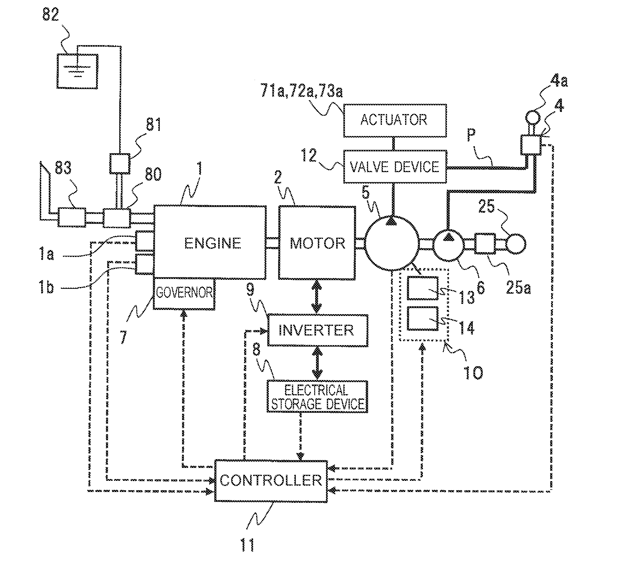
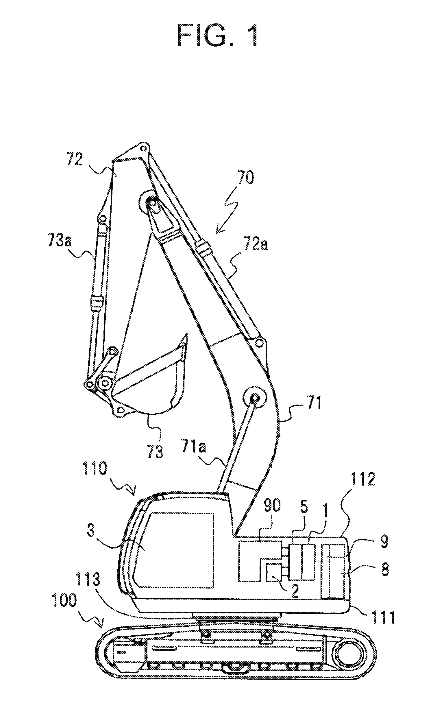
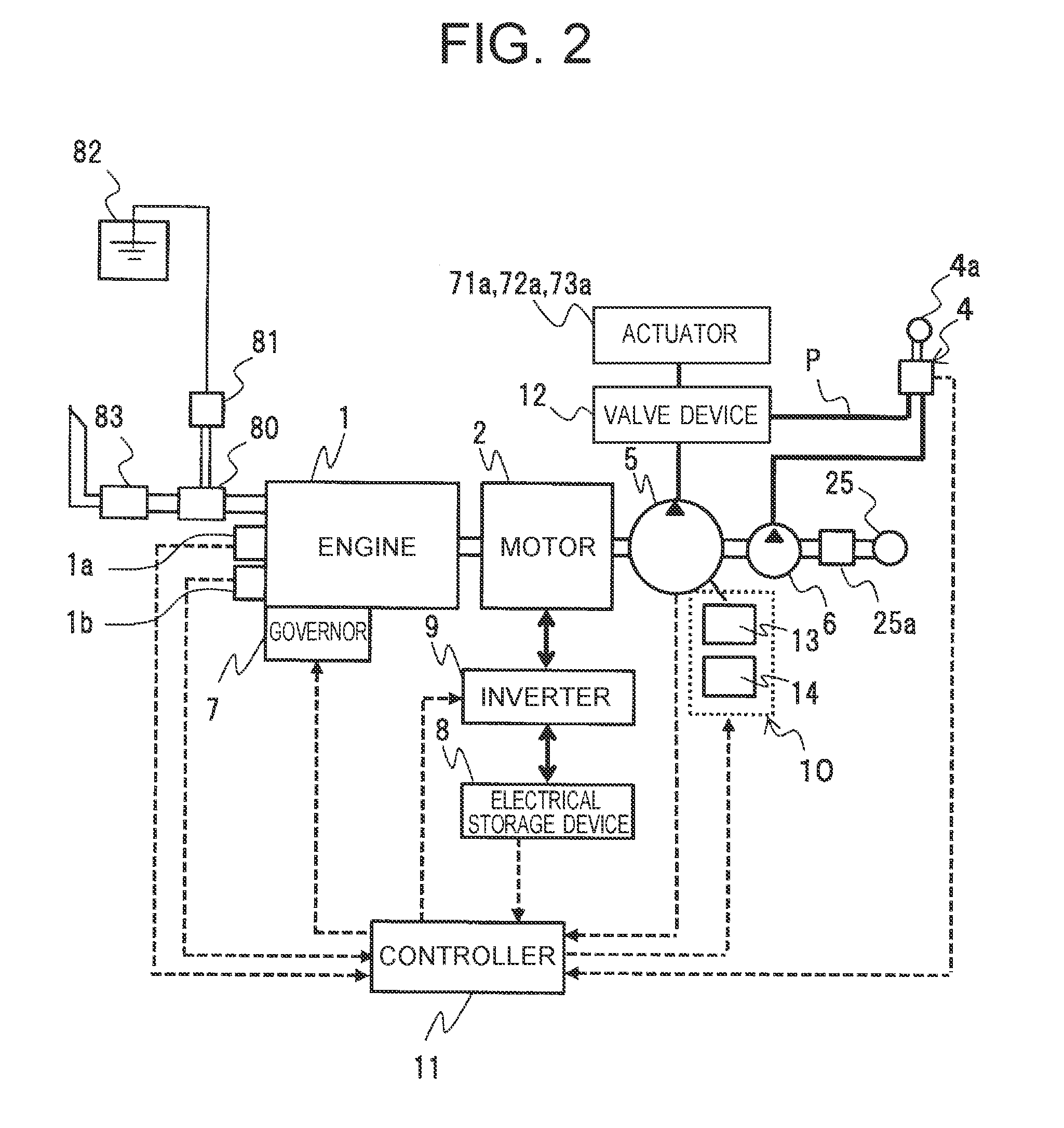
[0039]FIG. 1 is a diagram showing a configuration of a hybrid hydraulic excavator which has been given as one embodiment of a hybrid construction machine according to the present invention. FIG. 2 is a diagram explaining a configuration of essential parts of the hybrid hydraulic excavator according to a first embodiment of the present invention. FIG. 3 is a diagram explaining an internal configuration of a prime mover compartment of the hybrid hydraulic excavator according to the first embodiment of the present invention.

[0040]The first embodiment of the hybrid construction machine according to the present invention is applied to the hybrid hydraulic excavator (hereinafter, called a hydraulic excavator conveniently), for example, as shown in FIG. 1. This hydraulic excavator is provided with a travel base 100, a revolving superstructure 110 which has been provided on this travel base 100 via a revolving frame 111 so as to freely revolve, a revolving device 113 which is interposed bet...

second embodiment

[0097]FIG. 10 is a diagram explaining a configuration of an electrical storage device according to a second embodiment of the present invention and is a sectional diagram corresponding to FIG. 9. Incidentally, in the following description on the second embodiment of the present invention, the same numerals are assigned to the same parts as those in the above-mentioned first embodiment.

[0098]The second embodiment of the present invention is different from the aforementioned first embodiment in that while in the first embodiment, the eight battery modules 202 are arranged above the upper surface body 203A of the cooling plate 203 via the thermal conducting sheet 204 as shown in FIG. 8, FIG. 9, in the second embodiment, for example, as shown in FIG. 10, in the eight battery modules 202, the four battery modules 202 are arranged above an upper surface body 203A1 of a cooling plate 203E and the remaining four battery modules 202 are arranged under a lower surface body 203B1 of the coolin...

third embodiment

[0107]FIG. 11 is a diagram explaining a configuration of an electrical storage device according to a third embodiment of the present invention and is a sectional diagram corresponding to FIG. 9. Incidentally, in the following description on the third embodiment of the present invention, the same numerals are assigned to the same parts as those in the above-mentioned first embodiment.

[0108]The third embodiment of the present invention is different from the aforementioned first embodiment in that while in the first embodiment, the housing 220 is configured by the lower housing 221, the intermediate housing 222 and the upper housing 223 as shown in FIG. 7 to FIG. 9 and the upper surfaces of the lower housing 221 and the intermediate housing 222 are opened, in the third embodiment, for example, as shown in FIG. 11, a housing 220B is configured by a lower housing 221B and an upper housing 223B with the exception of the intermediate housing 222 and lower surfaces of the lower housing 221B...


PUM


Abstract

Provided is a hybrid construction machine which can improve temperature control efficiency of an electrical storage device. It includes an engine 1, an assisting electricity generation motor 2 which performs assistance of power for the engine 1 and electricity generation and an electrical storage device 8 which performs transfer of electric power with this assisting electricity generation motor 2. The electrical storage device 8 includes a plurality of battery cells 200, a housing 220 which covers the plurality of battery cells 200 in a state of leaving them separated, a cooling plate 203 which is attached to this housing 220 and performs heat exchange with the plurality of battery cells 200, and a projection 214 which is interposed between the housing 220 and the cooling plate 203 and hinders heat transfer between the housing 220 and the cooling plate 203.

Description

TECHNICAL FIELD[0001]The present invention relates to a hybrid construction machine hybrid construction machine provided with an electrical storage device which supplies electric power to prime movers such as a motor and an inverter and so forth.BACKGROUND ART[0002]In general, a construction machine such an a hydraulic excavator and so forth to be driven by an hydraulic system is provided with a hydraulic pump which makes maximum load work possible, and a large-sized engine which drives this hydraulic pump so as to cope with all kinds of work from light load work to heavy load work. In particular, in the hydraulic excavator, the maximum load is generated when the work such as excavation, loading and so forth of sediment is performed.[0003]The heavy load work on which such a maximum load is imposed is part of the overall work and the capacity of the engine is left over at the time of the light load work such as horizontal tow and so forth for levelling the ground. This is one of fact...

Claims


Application Information

Patent Timeline
IPC IPC(8): E02F9/20B60K1/04E02F9/08B60K6/485B60L11/18E02F3/32B60K6/28B60L50/16B60L50/64
CPCB60K2001/005Y02T10/6226E02F9/0866E02F3/32B60L11/1874E02F9/2091E02F9/2075Y10S903/903B60K1/04B60K6/28B60K6/485B60K11/04B60L11/14B60L11/18H01M2/10H01M10/625H01M10/6563H01M10/647H01M10/6556H01M10/6567H01M10/613H01M10/658B60Y2200/412E02F9/0858B60L1/003B60L2200/40H01M2220/20H01M10/615H01M10/6554B60L58/26B60L50/64Y02T10/62Y02T10/70Y02E60/10H01M50/249
Inventor KOHNO, RYUJITAKEUCHI, KENYOSHIHARA, SHIGEYUKI
Owner NIHON KENKI CO LTD
Learn More