Optical module

a technology of optical modules and optical couplings, applied in the field of optical modules, can solve the problems of large optical coupling loss, difficult integration of systems, and deterioration of system operation efficiency, and achieve the effects of reducing the loss of electric signals, reducing the loss of electrical signals, and extending bandwidth

Inactive Publication Date: 2016-07-21
ELECTRONICS & TELECOMM RES INST
View PDF5 Cites 1 Cited by
  • Summary
  • Abstract
  • Description
  • Claims
  • Application Information

AI Technical Summary

Benefits of technology

[0018]An optical module according to an exemplary embodiment of the present invention can simplify a production process by forming a transmission line in a glass rod.
[0019]Furt...

Problems solved by technology

However, as in a next generation information communication system that is formed with a large capacity parallel computer or an ATM switching system having a capacity of 1 Tb/s or more, as a large amount of information is transmitted and transmission speed is improved, when using such a metal cable, an electrical problem such as skew and electromagnetic interference (EMI) occurs and thus operation efficiency of the system is...

Method used


Image

  • Optical module
  • Optical module
  • Optical module

Examples


Embodiment Construction

[0024]In the following detailed description, only certain exemplary embodiments of the present invention have been shown and described, simply by way of illustration. As those skilled in the art would realize, the described embodiments may be modified in various different ways, all without departing from the spirit or scope of the present invention.

[0025]Accordingly, the drawings and description are to be regarded as illustrative in nature and not restrictive. Like reference numerals designate like elements throughout the specification.

[0026]Further, in the drawings, a size and thickness of each element are randomly represented for better understanding and ease of description, and the present invention is not limited thereto.

[0027]In addition, unless explicitly described to the contrary, the word “comprise” and variations such as “comprises” or “comprising” will be understood to imply the inclusion of stated elements but not the exclusion of any other elements.

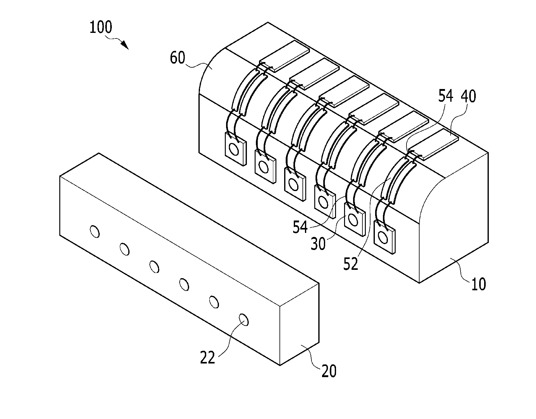
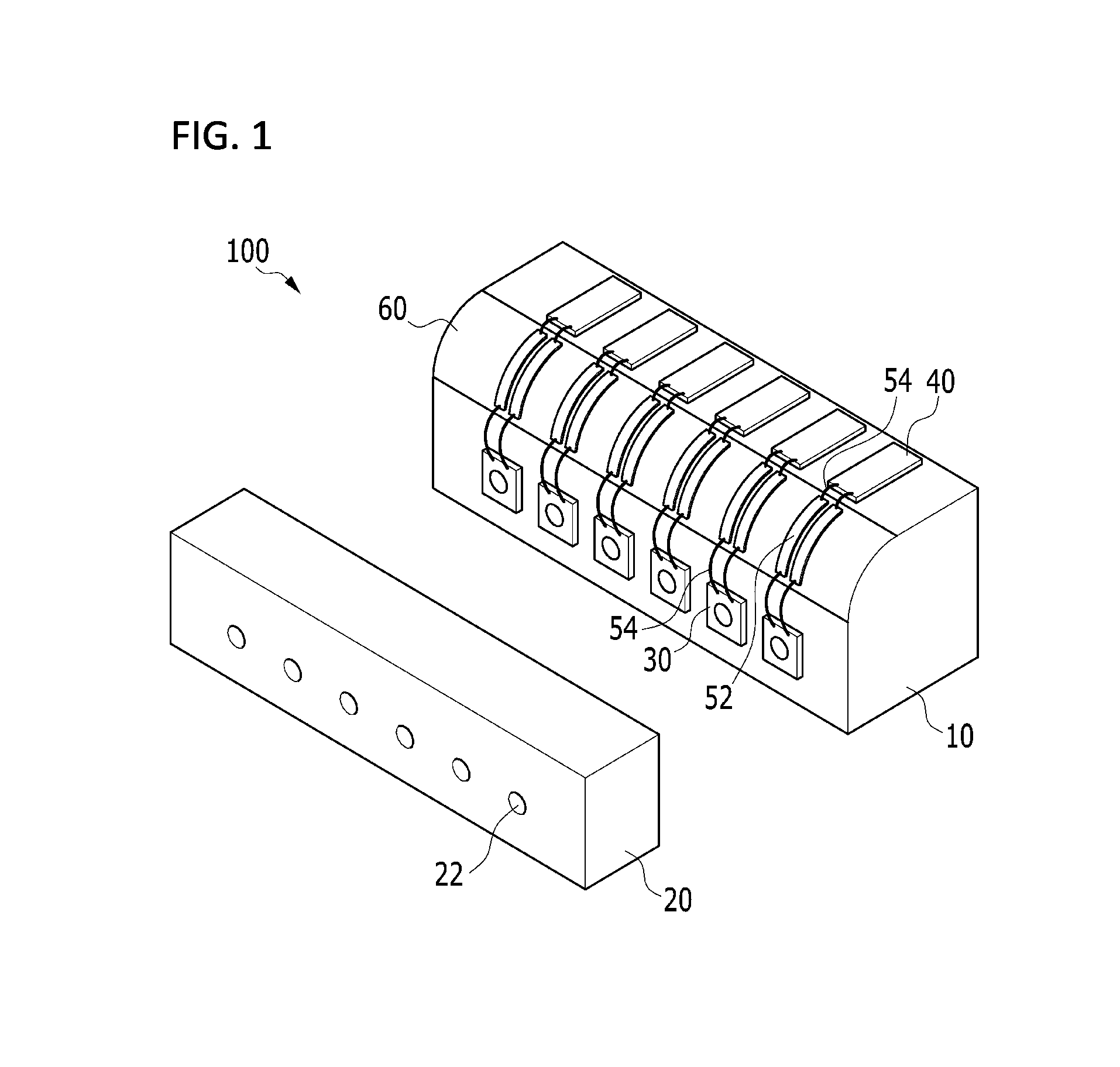
[0028]FIG. 1 is a pers...


PUM


Abstract

An optical module includes: a circuit board having a surface in which an electronic element is mounted; an optical waveguide array in which a plurality of optical waveguides are formed; an optical element in which an optical signal that is transmitted and received from and to the optical waveguide is input and that is mounted at a side surface of the circuit board; and a connection member that connects the optical element and the electronic element, wherein a connection portion of a side surface of the circuit board in which the connection member is received has a curved shape.

Description

CROSS-REFERENCE TO RELATED APPLICATION[0001]This application claims priority to and the benefit of Korean Patent Application No. 10-2015-0007148 filed in the Korean Intellectual Property Office on Jan. 15, 2015, the entire contents of which are incorporated herein by reference.BACKGROUND OF THE INVENTION[0002](a) Field of the Invention[0003]The present invention relates to an optical module. More particularly, the present invention relates to an optical module that transfers an electric signal that is generated according to an applied optical signal to a circuit board.[0004](b) Description of the Related Art[0005]In general, in a low speed system, a connection between circuit boards and between chips or between systems is performed through a metal electrical cable. However, as in a next generation information communication system that is formed with a large capacity parallel computer or an ATM switching system having a capacity of 1 Tb / s or more, as a large amount of information is ...

Claims


Application Information

Patent Timeline
IPC IPC(8): G02B6/42G02B6/43
CPCG02B6/4274G02B6/43G02B6/4245G02B6/4204G02B6/4249G02B6/428G02B6/3608G02B6/3636G02B6/4281
Inventor LEE, JONG JIN
Owner ELECTRONICS & TELECOMM RES INST
Why Eureka
Try Eureka