
Energy-Efficient and Environmentally Advanced Configurations for Naptha Hydrotreating Process

a technology of naphtha hydrotreating and hydrotreating water, which is applied in the direction of hydrocarbon oil treatment products, sustainable manufacturing/processing, lighting and heating apparatus, etc., can solve the problems of large amount of heating utilities, large quantity of undesirable emissions, and catastrophic environmental emissions, so as to reduce the amount of green house gas emissions, less energy consumption, and less capital investmen

Active Publication Date: 2016-07-14
SAUDI ARABIAN OIL CO
View PDF0 Cites 3 Cited by
  • Summary
  • Abstract
  • Description
  • Claims
  • Application Information

AI Technical Summary

Benefits of technology

This configuration significantly reduces energy-based emissions by over a million tons of CO2 over the plant's lifetime, decreases utility and capital expenses, and enhances energy efficiency while maintaining effective desulfurization and denitrogenation processes.

Problems solved by technology

The naphtha and other distillates, however, in their initial form include numerous undesirable materials such as sulfur, nitrogen, olefins, and aromatics.
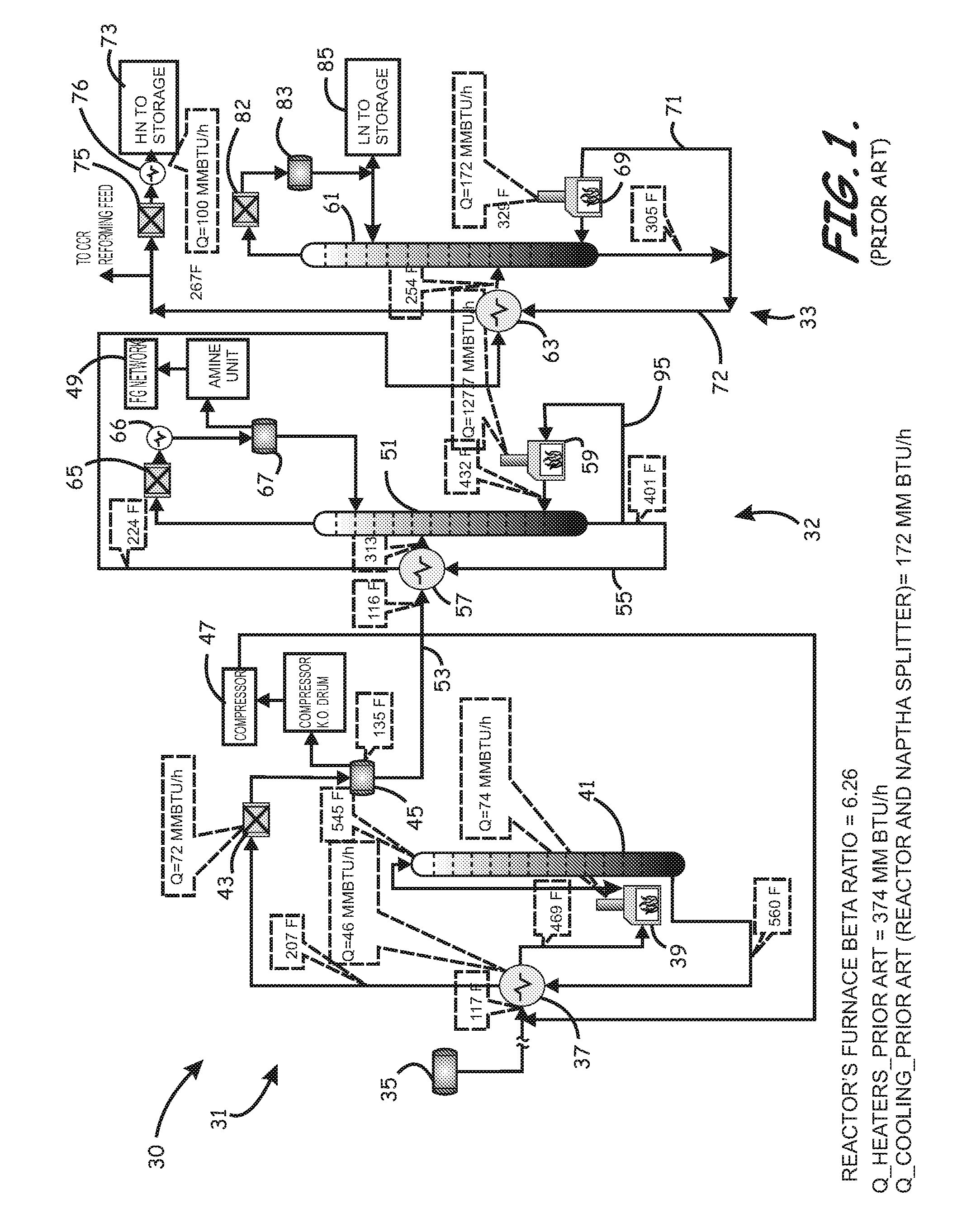
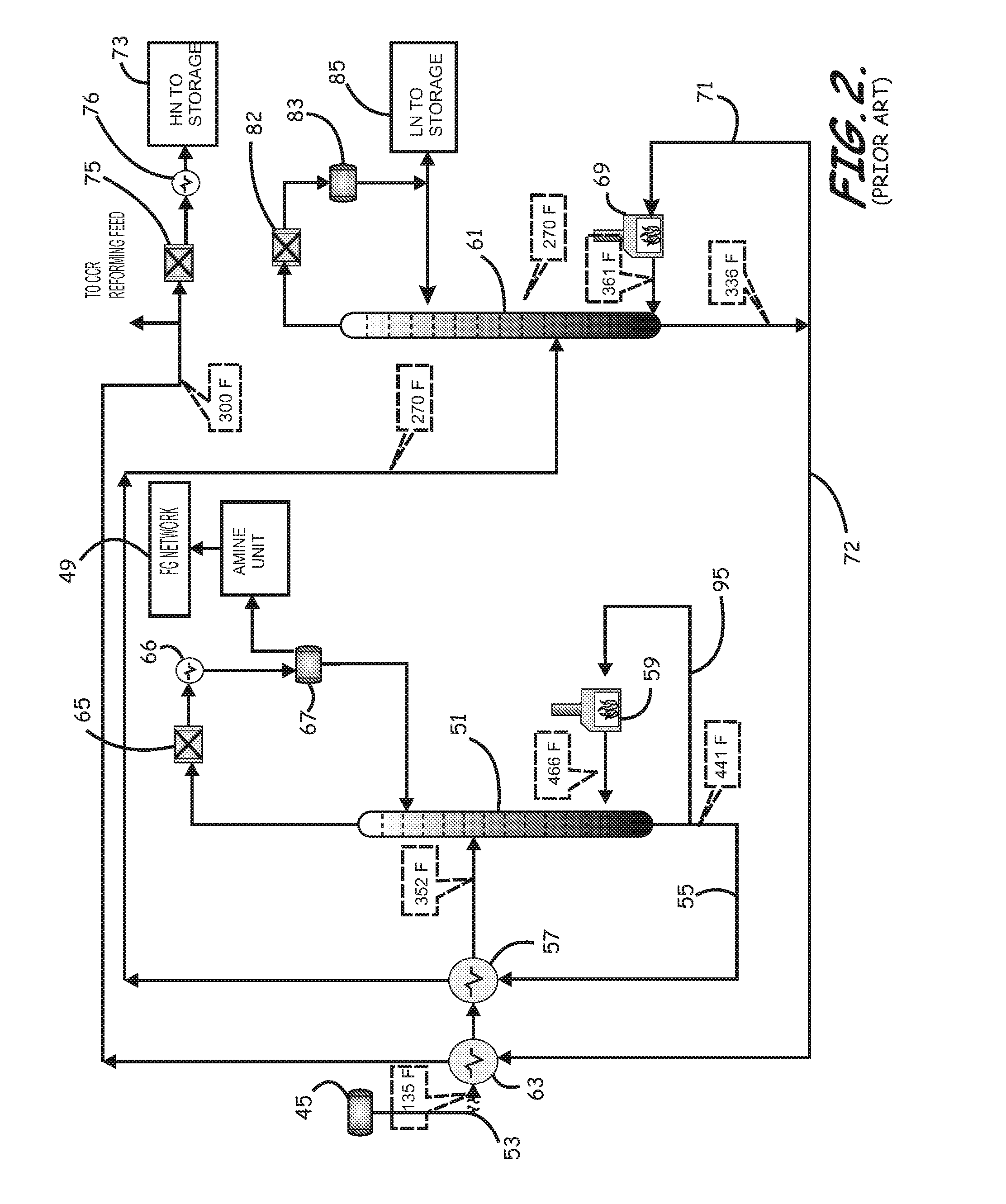
Although very simple, the contaminants stripper and a naphtha splitter sections however, use huge amounts of heating utilities, most of the time in the form of fossil fuel consumed in re-firing units assigned to each of the sections.
These fired heaters, used to supply the required heating utility, also produce a large quantity of undesirable emissions.
In some parts of the world, such emissions are catastrophic to the environment.
Air coolers are capital and maintenance intensive equipment and water cooling, and in some parts of the world have significant availability and maintenance problems, as well.
Recognized by the inventors is that, even in view of such difficulties surrounding the use of external utilities, such conventional energy recovery methods fail to optimize waste heat recovery within and between the processes.

Method used


Image

  • Energy-Efficient and Environmentally Advanced Configurations for Naptha Hydrotreating Process
  • Energy-Efficient and Environmentally Advanced Configurations for Naptha Hydrotreating Process
  • Energy-Efficient and Environmentally Advanced Configurations for Naptha Hydrotreating Process

Examples


Embodiment Construction

[0046]The present invention will now be described more fully hereinafter with reference to the accompanying drawings, which illustrate embodiments of the invention. This invention may, however, be embodied in many different forms and should not be construed as limited to the illustrated embodiments set forth herein. Rather, these embodiments are provided so that this disclosure will be thorough and complete, and will fully convey the scope of the invention to those skilled in the art. Like numbers refer to like elements throughout. Prime notation, if used, indicates similar elements in alternative embodiments.

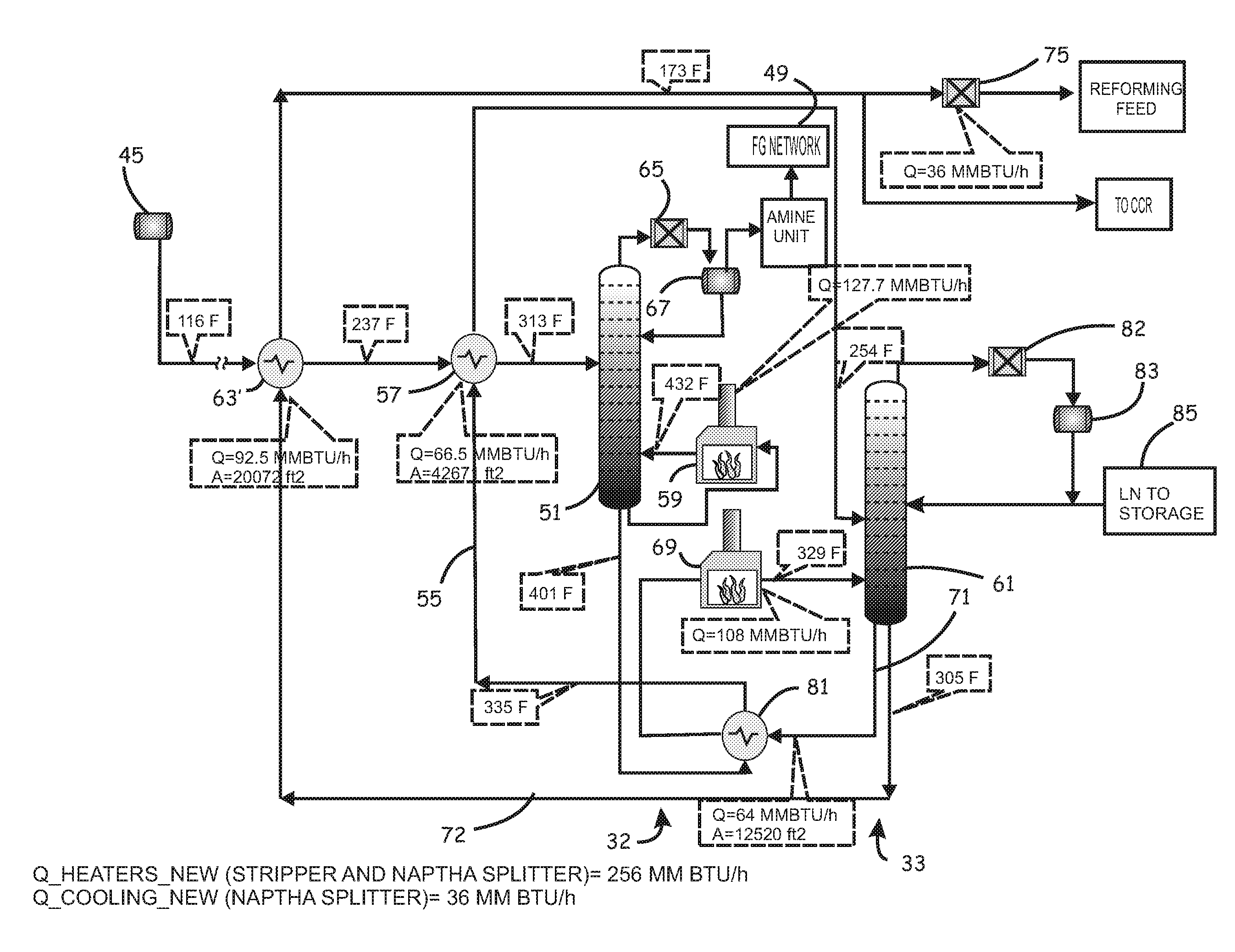
[0047]FIGS. 1-8 provide examples of simulation files including stream data and detailed simulation results of conventional configurations and those according to various embodiment of the present invention, to illustrate various benefits without limiting the various embodiments of the invention's new energy efficient and environmentally conscious advanced configurations for the ...


PUM

PropertyMeasurementUnit
temperatureaaaaaaaaaa
reaction ratesaaaaaaaaaa

Abstract

Systems and methods of hydrotreating different naphtha feed stocks destined for a refining reforming unit and other applications with less energy consumption than conventionally possible, while producing less greenhouse gas emissions, and / or using a lesser number of heaters and correspondingly less capital investment in such heaters, air coolers, and water coolers, are provided. According to the more examples of such systems and methods, such reductions are accomplished by directly integrating a naphtha stripping process section with a naphtha splitting process section. Additional reductions can also be accomplished through directly integrating a naphtha hydrotreat reaction process section with the naphtha stripping process section.

Description

CROSS-REFERENCE TO RELATED PATENT APPLICATIONS[0001]This application is a continuation of and claims priority to U.S. patent application Ser. No. 13 / 099,144 titled “Energy-Efficient and Environmentally Advanced Configurations for Naptha Hydrotreating Process” and filed on May 2, 2011BACKGROUND OF THE INVENTION[0002]1. Field of the Invention[0003]The present invention relates in general to the field of naphtha hydrotreating processes, and in particular, to systems and methods related to waste heat recovery for naphtha hydrotreating (NHT) processes for the desulfurization of naphtha.[0004]2. Description of the Related Art[0005]A petroleum refinery generally includes multiple separate unit operations and processes. One of the operations / processes includes the continuous distillation of petroleum to form a liquid distillate called naphtha which forms a major component of the refineries' product. After extraction through distillation, naphtha is generally further processed in catalytic r...

Claims


Application Information

Patent Timeline
Patent Type & Authority Applications(United States)
IPC IPC(8): F28D21/00B23P15/26
CPCF28D21/0012F28D2021/0059B23P15/26C10G2300/1044C10G2400/02C10G45/04Y02P30/00
Inventor NOURELDIN, MAHMOUD BAHYBUNAIYAN, AHMED SALEH
Owner SAUDI ARABIAN OIL CO
Learn More