
Mobile Terminal Charger

Active Publication Date: 2016-07-07
XIAN ZHONGXING NEW SOFTWARE
View PDF4 Cites 15 Cited by
  • Summary
  • Abstract
  • Description
  • Claims
  • Application Information

AI Technical Summary

Benefits of technology

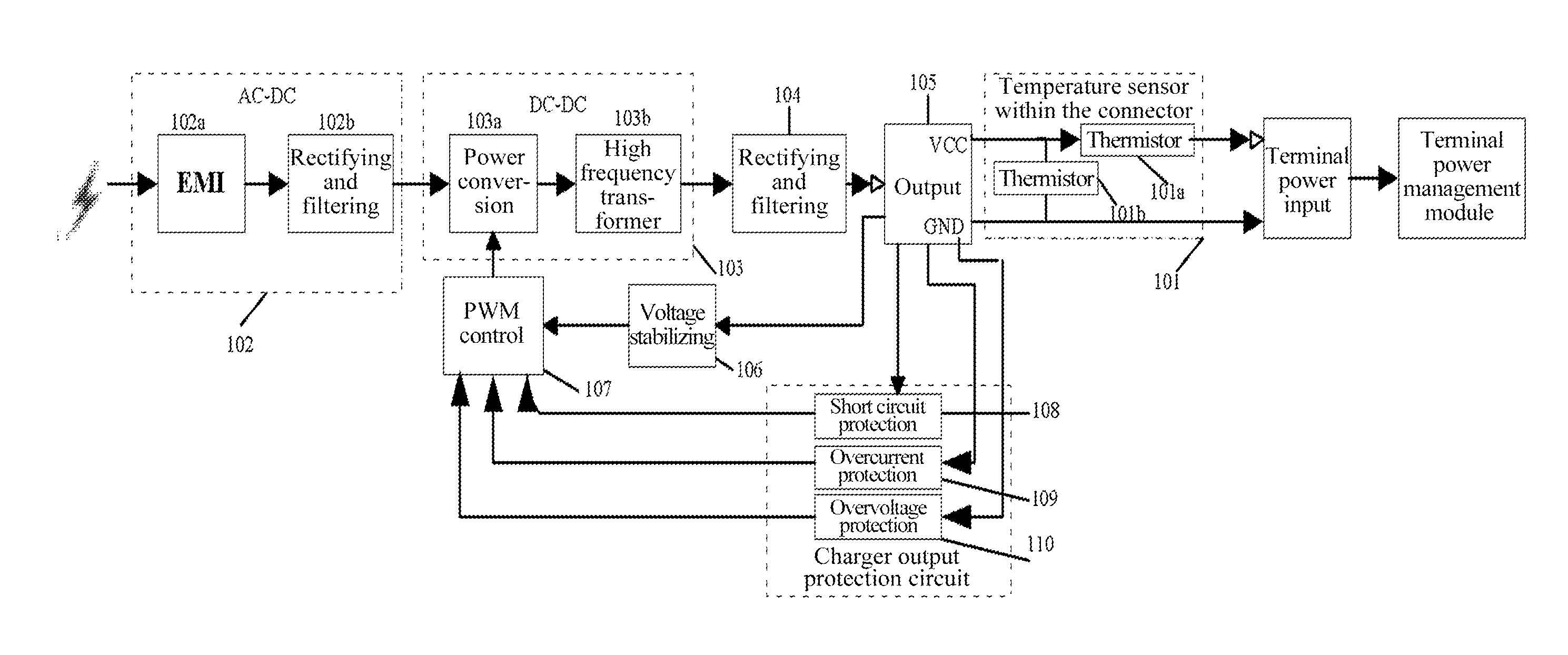
The present patent provides a mobile terminal charger to prevent safety issues that arise when charging cell phones. The charger has a thermistor mounted on the connector head that detects abnormal temperature increases and alters the resistance of the charger loop resistor. This prevents the charger from outputting excessive power and protects the data line and charger from damage. The technical effect of this invention is to enhance the safety of mobile charging.

Problems solved by technology

In the charging process with large current, many terminal users have encountered safety problem that the connector of the output terminal of the charger is burnt melted after the occurrence of micro-short circuit when the cell phone is charging, particularly for the current general connector of the Micro Universal Serial Bus recommended by the globe, due to the limit of structure and size, when in use by the user, a large amount of conductive liquid and metal powder is formed by the entry of foreign matter, the plug and the socket being damaged by slantingly inserting and pulling, the plug being bent and broken due to excessive force, resulting in the micro-short circuit of data line or charger within the plug; the micro-short circuit cannot achieve the protection condition of charger short circuit, causing the charger to continuously output power which is changed to heat at the plug of data line, finally resulting in that the data line or the charger plug or the cell phone interface are heated to melt, smoke and be on fire, etc.
The mobile terminals of current brands in the market all have the similar problem such that the user worries about the safety when using the cell phone, more seriously causing damage to the human body and property of the user.
Such problem is an incident of product safety, and even the national law prescribes that all the products will be recalled with severe punishment if the malfunction reaches a certain level.
As the battery capacity of the terminal products gets larger, the ratio of the occurrence and the influence of such problem get severe, so the solution for such problem gets urgent.
The temperature protection for the charger and the terminal interface has not been implemented, but such problem is generally occurred on the market.

Method used


Image

  • Mobile Terminal Charger
  • Mobile Terminal Charger
  • Mobile Terminal Charger

Examples


example 1

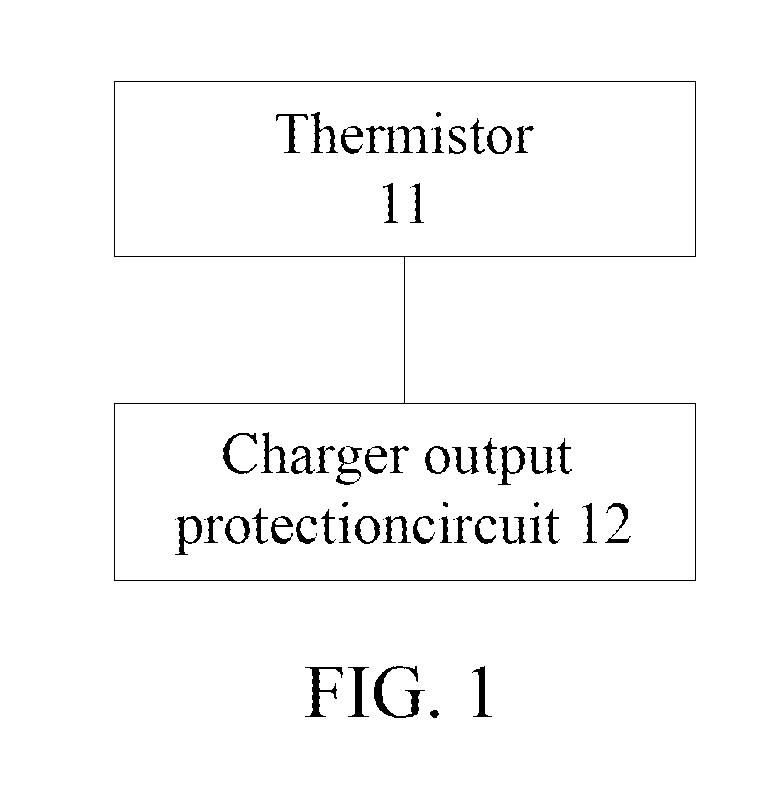
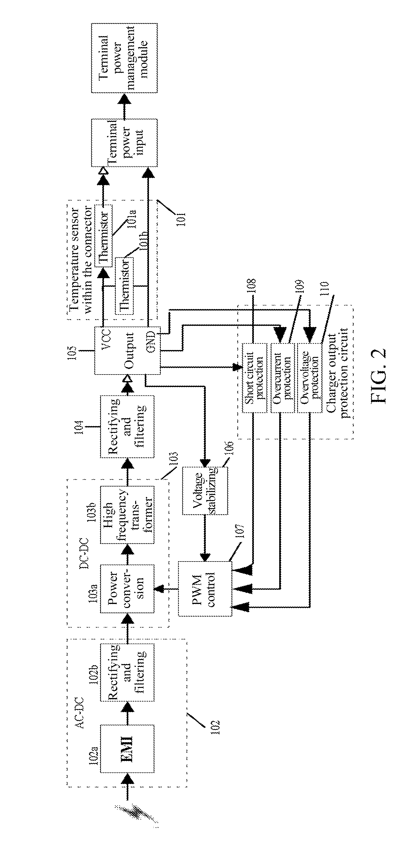
[0024]After the occurrence of micro-short circuit, with respect to whether it could be protected in designing to cut off the power loop to avoid heating, no scheme is feasible in view of the interior of the charger. If the temperature detection is introduced from the interior of the head of the connector to the interior of the charger for controlling, the line is longer with high cost and the temperature detection is inaccurate. Thus, the embodiments of the present document provide a mobile terminal charger, as shown in FIG. 1, comprising at least a thermistor 11, and a charger output protection circuit 12, wherein:[0025]the thermistor 11 mounted on a head of a connector accesses a charger circuit via a charger direct current (DC) cable, constitutes a charger loop resistor with the resistor in the charger; and[0026]a charger output protection circuit 12 cuts off or reduces the output power of the charger when the resistance of the charger loop resistor is less than the overcurrent p...


PUM


Abstract

A mobile terminal charger relates to the field of mobile terminals such as cell phone and data card with battery charging. The mobile terminal charger comprises: a thermistor and a charger output protection circuit, wherein the thermistor mounted on a head of a connector accesses a charger circuit via a charger direct current (DC) cable, constitutes a charger loop resistor with the resistor in the charger; and the charger output protection circuit cuts off or reduces the output power of the charger when the resistance of the charger loop resistor is less than the overcurrent protection threshold value.

Description

TECHNICAL FIELD[0001]The present document relates to the field of mobile terminals such as cell phone and data cards with battery charging, and more particularly, to a mobile terminal charger.BACKGROUND OF THE RELATED ART[0002]With the development of mobile terminal technology, the function required by the user gets more, the screen size gets bigger, and the battery capacity required by terminals also gets more, so the charger power for charging the cell phone gets higher. In the charging process with large current, many terminal users have encountered safety problem that the connector of the output terminal of the charger is burnt melted after the occurrence of micro-short circuit when the cell phone is charging, particularly for the current general connector of the Micro Universal Serial Bus recommended by the globe, due to the limit of structure and size, when in use by the user, a large amount of conductive liquid and metal powder is formed by the entry of foreign matter, the pl...

Claims


Application Information

Patent Timeline
IPC IPC(8): H02J7/00H02H7/18H02H3/08
CPCH02J7/0029H02J7/0042H02J7/0052H02J2007/0039H02H3/085H02H7/18H02J7/007H02J7/0031H02J7/00304H02J7/00308H02J7/00309H02J7/00
Inventor LIANG, XILIN
Owner XIAN ZHONGXING NEW SOFTWARE
Learn More