
Valve device for a motor vehicle

Active Publication Date: 2016-07-07
VITESCO TECH GMBH
View PDF5 Cites 0 Cited by
  • Summary
  • Abstract
  • Description
  • Claims
  • Application Information

AI Technical Summary

Benefits of technology

The valve device described in this patent text has a small cross section in the flow duct, which makes it possible to have a larger valve seat and flap without the need to develop new parts. This design improves regulability and reduces turbulence, and it can be easily adapted to different usage situations by adjusting the cross section of the flow duct. The design also makes it simple to install and replace the valve seat and flap.

Problems solved by technology

Since the adaptation of flap and valve seat with regard to regulation involves considerably less outlay, the use of existing parts leads to considerable simplification.

Method used


Image

  • Valve device for a motor vehicle
  • Valve device for a motor vehicle
  • Valve device for a motor vehicle

Examples


Embodiment Construction

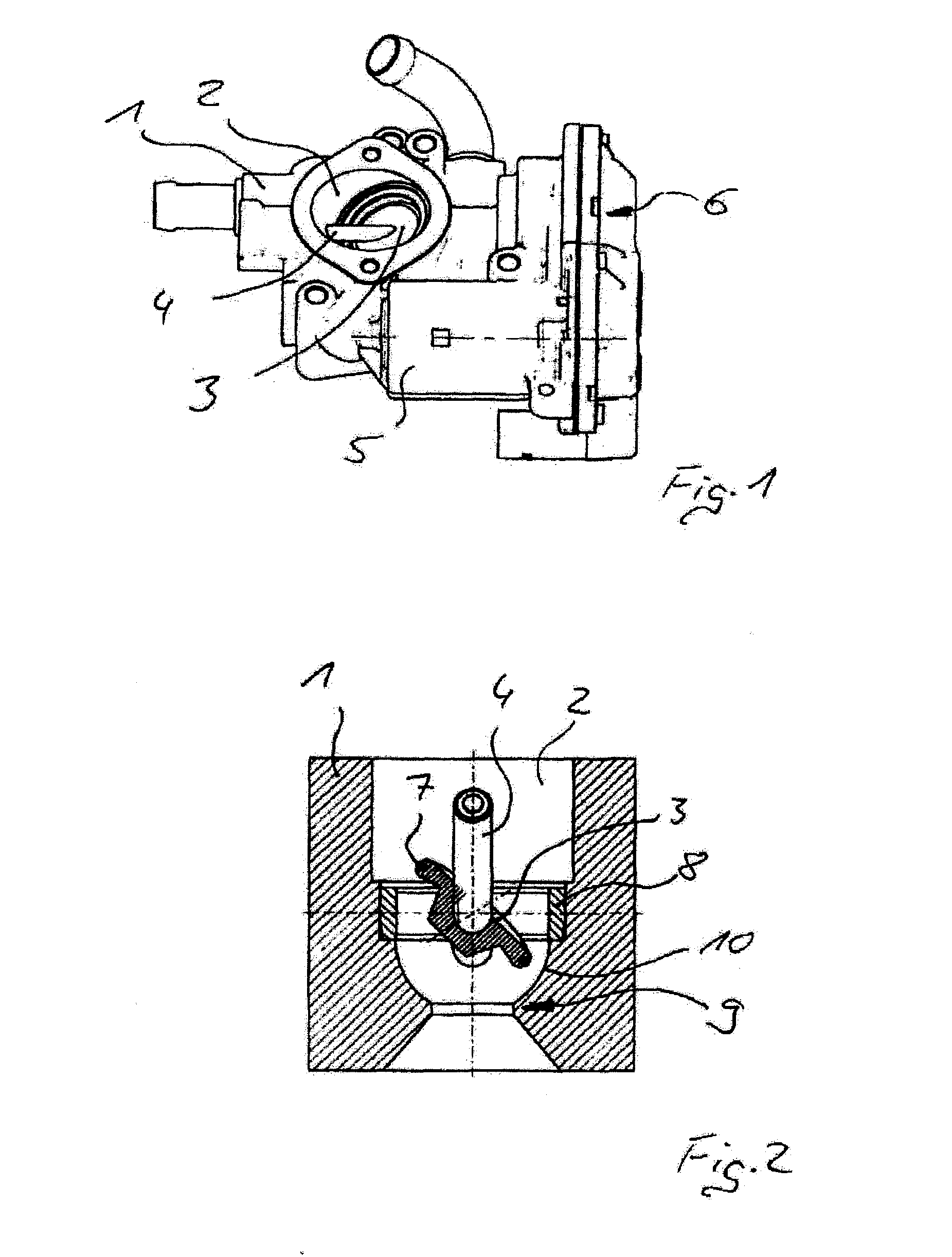
[0022]FIG. 1 shows an exhaust-gas recirculation valve having a housing 1, and having a flow duct 2, which is situated in the housing and in which there is arranged a disk-shaped flap 3. The flap 3 is fixedly connected to a spindle 4, and the spindle 4 is rotatably mounted in the housing 1. The spindle 4 is driven by an electric motor 5 arranged in the housing 1, wherein a gearing 6 is interconnected between the spindle 4 and electric motor 5.

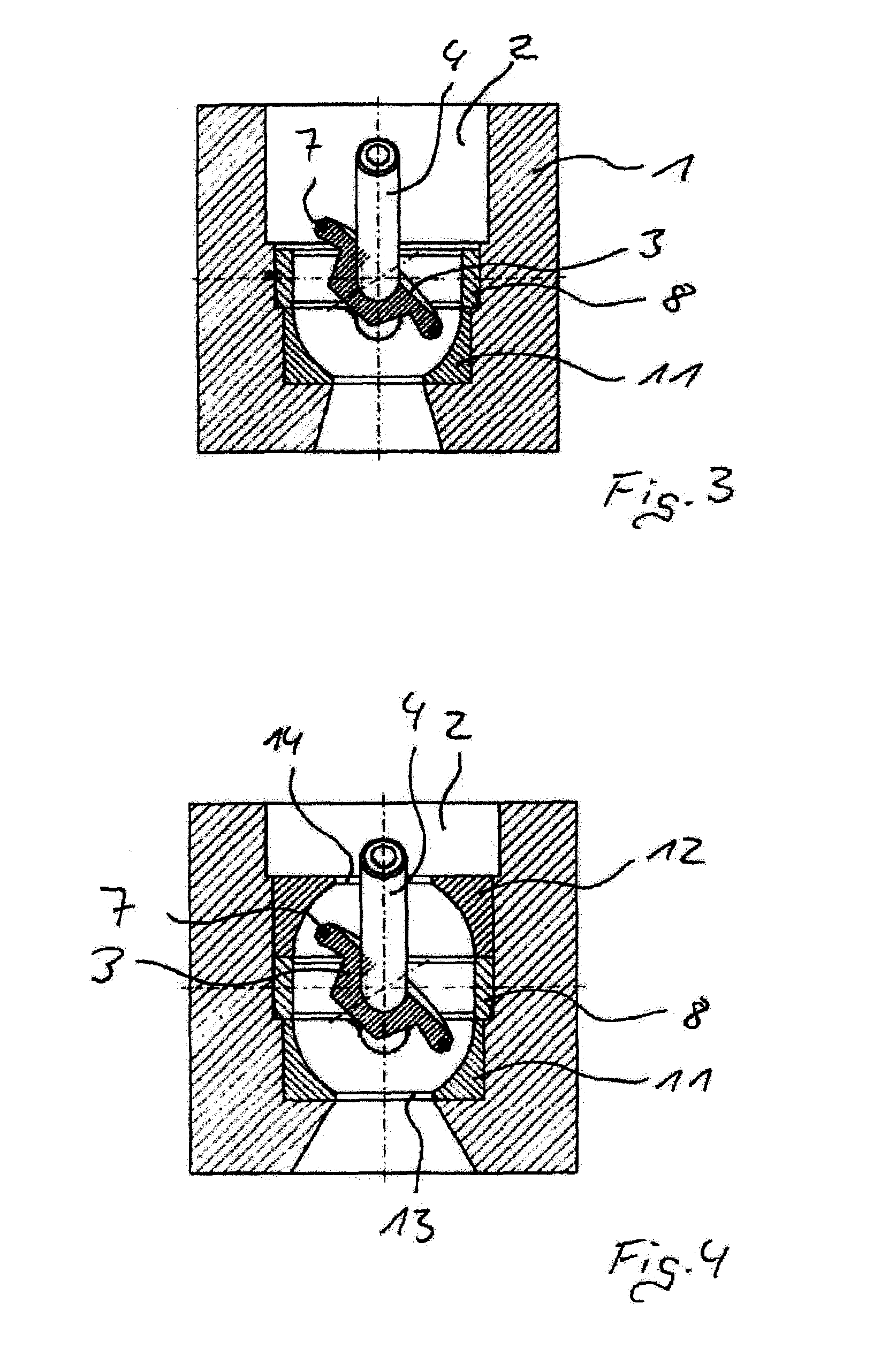
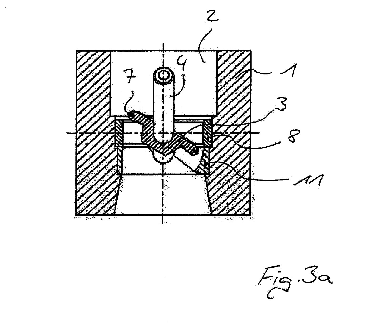
[0023]FIG. 2 shows a part of the flow duct 2 as per FIG. 1 in section. The disk-shaped flap 3 is fastened rotationally conjointly to the spindle 4 by way of a welded connection. In the illustration shown, the flap 3 is approximately halfway open. The sealing is realized here by way of a sealing ring 7, which is arranged in a groove of the flap 3. The sealing ring 7 seals off the flow duct 2 with respect to the inner wall of a ring 8, which is inserted into the flow duct 2, such that the ring acts as a valve seat 8. In the event of a rotation of ...


PUM


Abstract

A valve device for a motor vehicle includes: a housing; a flow duct situated in the housing; and a flap arranged in the flow duct to close off the flow duct, the flap having regions in which a shaft penetrating the flap is fastened. The shaft is rotatably mounted in the housing and a valve seat is arranged in the flow duct, the valve seat being in contact with the flap in the closed position thereof. At least one portion of the flow duct adjacent to the valve seat has a cross section smaller than the inside diameter of the valve seat.

Description

CROSS-REFERENCE TO RELATED APPLICATIONS[0001]This is a U.S. national stage of application No. PCT / EP2013 / 075708, filed on 5 Dec. 2013, which claims priority to the German Application No. DE 10 2012 224 093.4 filed 20 Dec. 2012, the content of both incorporated herein by reference.BACKGROUND OF THE INVENTION[0002]1. Field of the Invention[0003]The invention relates to a valve device for a motor vehicle, having a housing, having a flow duct situated in the housing, having a flap which is arranged in the flow duct and which serves for closing off the flow duct, wherein the flap is fastened to a spindle, and the spindle is mounted rotatably in the housing, and having a valve seat which is arranged in the flow duct and which is in contact with the flap when the latter is in its closed position.[0004]2. Related Art[0005]Valve devices are used, for example, as throttle flap connectors or exhaust life gas recirculation valves, and have long been known. By making use of the rotatably mounted...

Claims


Application Information

Patent Timeline
IPC IPC(8): F02M26/70F02M26/72F16K47/08F16K1/226F16K27/02
CPCF02M26/70F16K1/2261F02M26/72F16K47/08F16K27/0218F02M26/68
Inventor MONTIGNY, SYBILLEVON WILLICH, JOACHIMKOHLEN, PETER
Owner VITESCO TECH GMBH
Learn More