Control system for four-wheel drive vehicle
- Summary
- Abstract
- Description
- Claims
- Application Information
AI Technical Summary
Benefits of technology
Problems solved by technology
Method used
Image
Examples
first embodiment
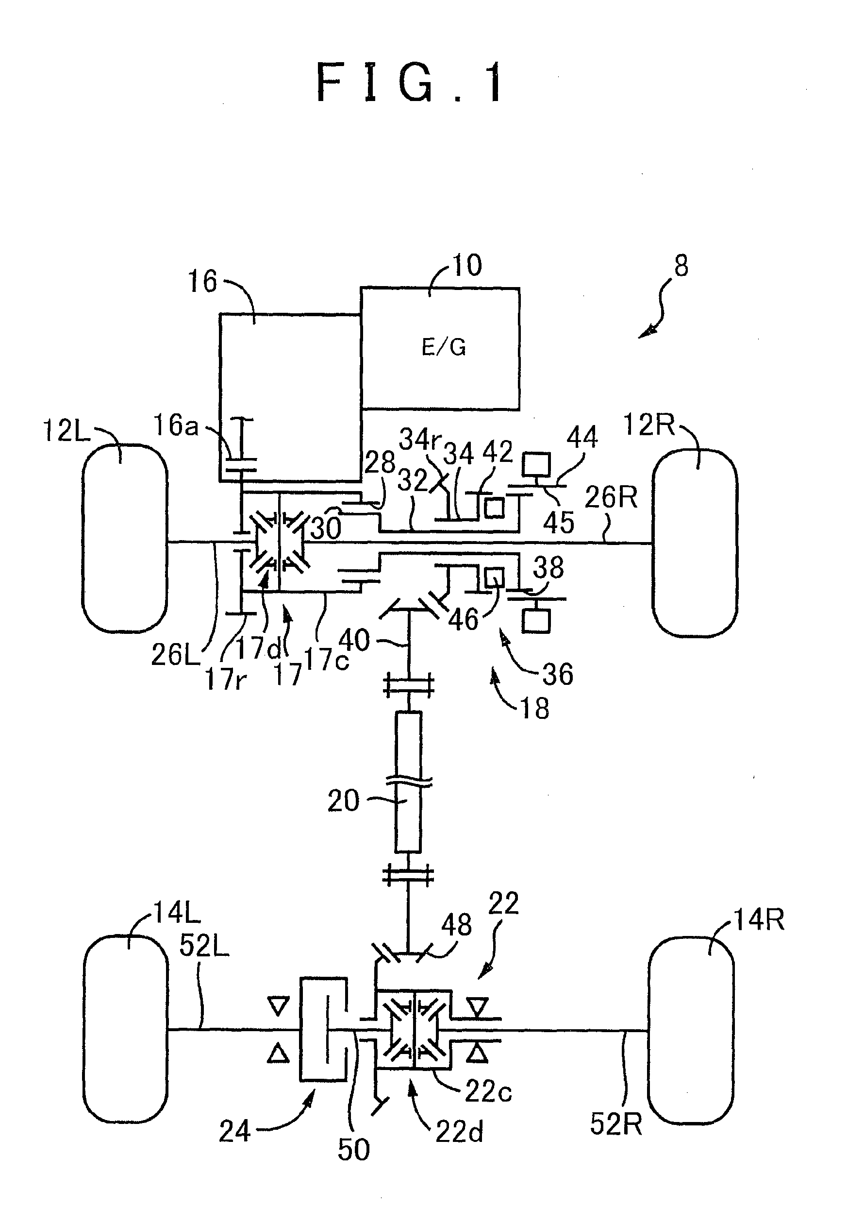
[0029]FIG. 1 is a skeleton view schematically explaining the configuration of a 4WD vehicle 8 to which the invention is suitably applied. In FIG. 1, the 4WD vehicle 8 is an FF vehicle that uses an E / G 10 as a drive source, and includes a power T / M path that transmits power of the E / G 10 to front wheels 12L and 12R (referred to as front wheels 12 in the case where it is not necessary to differentiate between them), and a power T / M path that transmits the power of the E / G 10 to rear wheels 14L and 14R (referred to as rear wheels 14 in the case where it is not necessary to differentiate between them). The 4WD vehicle 8 includes an automatic T / M 16, a front differential gear 17, a transfer 18, a propeller shaft 20, a rear differential gear 22, and a coupling 24. Although not shown in FIG. 1, a torque converter as a fluid power T / M device is provided between the E / G 10 and the automatic T / M 16. Note that the rear wheel 14 corresponds to an auxiliary drive wheel of the invention to which ...
second embodiment
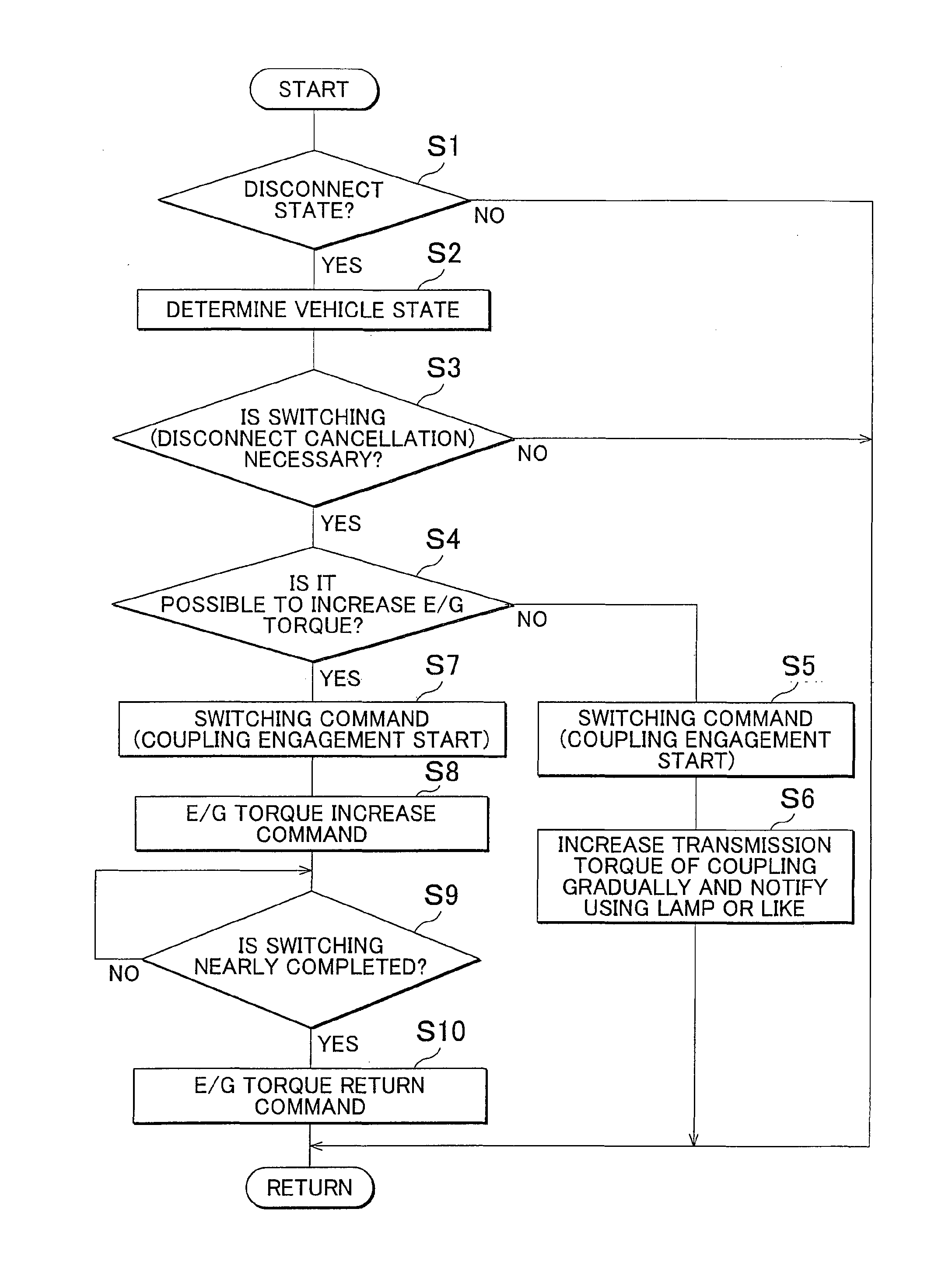
[0071]In the embodiment described above, in the case where it is difficult to increase the E / G torque Te during the switching from the 2WD_d running to the 4WD running, the T / M torque of the coupling 24 is reduced to be lower than that in the case where it is possible to increase the E / G torque Te. However, in the present embodiment, when the running is switched from the 2WD_d running to the 4WD running or the 2WD running, the speed ratio of the automatic T / M 16 is changed to the increase side of the driving force, and the increase in rotational inertia is thereby canceled.
[0072]In the case where the switching availability determination section 118 determines that it is difficult to increase the E / G torque Te when the running is switched from the 2WD_d running to the 4WD running or the 2WD running, the alternative control section 119 of the present embodiment outputs to the gear shift control section 112 a command to change the speed ratio of the automatic T / M 16 to the increase sid...
third embodiment
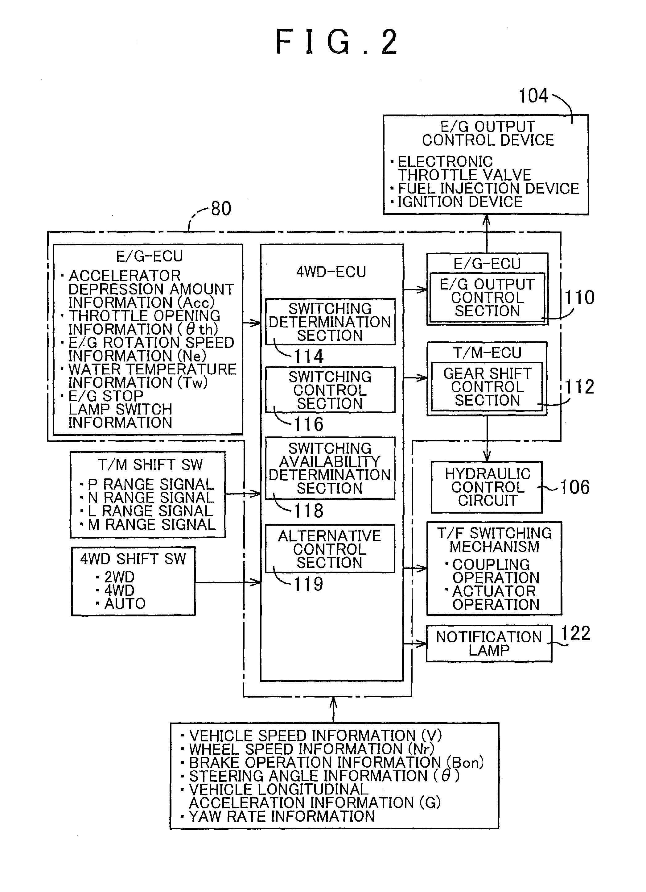
[0079]FIG. 7 is a functional block diagram explaining the control system of an ECU 150 as still another embodiment of the invention and also explaining the principal portion of the control function. When the ECU 150 in FIG. 7 is compared with the ECU 80 in FIG. 2, the ECU 150 additionally includes a switching restriction section 120 as its function. Hereinbelow, the switching restriction section 120 additionally provided in the present embodiment will be described.
[0080]When the switching availability determination section 118 determines that it is difficult to increase the E / G torque Te, in the case where the vehicle runs in the 4WD running state or the 2WD running state, the switching restriction section 120 prohibits the switching to the 2WD_d running even when the switching to the 2WD_d running is determined. Alternatively, the switching restriction section 120 tightens a condition for the switching to the 2WD_d running. The switching restriction section 120 tightens the conditi...
PUM
 Abstract
Description
Claims
Application Information
 - R&D
- Intellectual Property
- Life Sciences
- Materials
- Tech Scout
- Unparalleled Data Quality
- Higher Quality Content
- 60% Fewer Hallucinations
Browse by: Latest US Patents, China's latest patents, Technical Efficacy Thesaurus, Application Domain, Technology Topic, Popular Technical Reports.
© 2025 PatSnap. All rights reserved.Legal|Privacy policy|Modern Slavery Act Transparency Statement|Sitemap|About US| Contact US: help@patsnap.com


