Automated Analyzer and Method for Lifting and Lowering Rod-Like Member in Automated Analyzer

an analyzer and automatic technology, applied in the field of automatic analyzer and a method for lifting and lowering a rodlike member in the automated analyzer, can solve the problems of excessive liquid droplets adhering to the tip, uneven absolute amount of dispensed liquid, contamination of machinery, etc., and achieves the effect of reducing liquid droplets adhering and high analytical accuracy

Active Publication Date: 2016-06-30
JEOL LTD
View PDF3 Cites 6 Cited by
  • Summary
  • Abstract
  • Description
  • Claims
  • Application Information

AI Technical Summary

Benefits of technology

The patent aims to reduce the liquid drops on the end of a rod-like object and improve the accuracy of analysis.

Problems solved by technology

Incidentally, during the above dispensing procedures, excessive liquid droplets adhere to the tip portion of the probe since the probe lifts and lowers relative to the container and the tip of the probe makes contact with the specimen, reagent or cleaning liquid.
In addition, when the excessive liquid droplets are admixed to, for example, the reaction container, there is unevenness in the absolute amount of the dispensed liquid.
In addition, during the movement of the probe, contamination of machinery is also generated due to scattering the excessive liquid droplets.

Method used


Image

  • Automated Analyzer and Method for Lifting and Lowering Rod-Like Member in Automated Analyzer
  • Automated Analyzer and Method for Lifting and Lowering Rod-Like Member in Automated Analyzer
  • Automated Analyzer and Method for Lifting and Lowering Rod-Like Member in Automated Analyzer

Examples


first exemplary embodiment

1. First Exemplary Embodiment

1-1. Configuration of Automated Analyzer

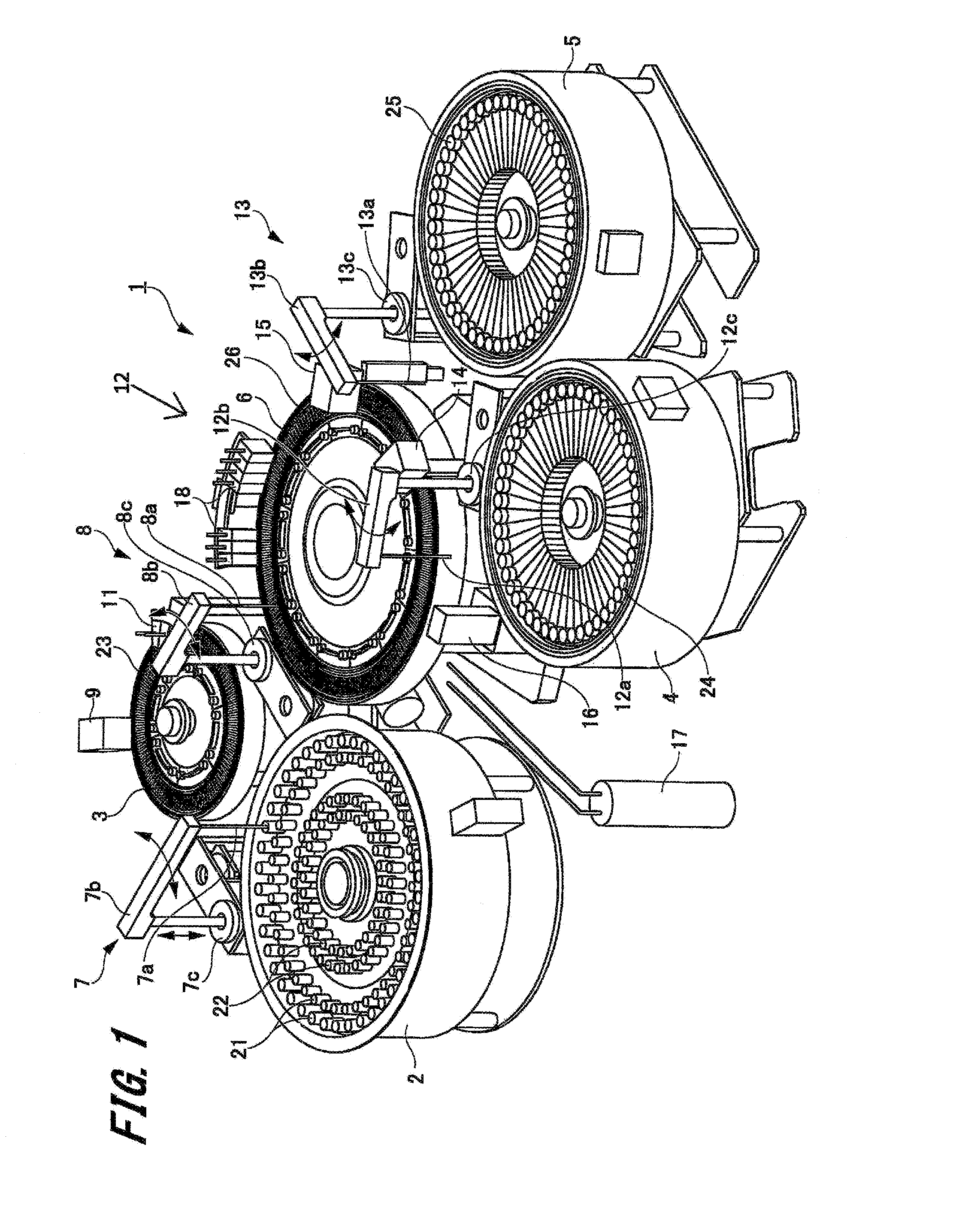
[0034]First, a first exemplary embodiment of the automated analyzer of the present invention (hereinafter, referred to as “the present exemplary embodiment”) will be described by referring to FIG. 1.

[0035]FIG. 1 is a perspective schematic view of the automated analyzer of the present exemplary embodiment.

[0036]The device shown in FIG. 1 is a biochemical analyzer applied as one example of the automated analyzer 1 of the present invention. The biochemical analyzer is a device for automatedally measuring the amount of a certain component contained in a biological sample such as blood or urine.

[0037]As shown in FIG. 1, the automated analyzer 1 includes a sample turntable 2, a dilution turntable 3, a first reagent turntable 4, a second reagent turntable 5, and a reaction turntable 6. In addition, the automated analyzer 1 includes a sample diluting dispensing mechanism 7, a sampling dispensing mechanism 8, a dilution and...

second exemplary embodiment

Effects of Second Exemplary Embodiment

[0192]The above-described automated analyzer of the second embodiment has the configuration in which there are performed the stirring operation that stirs the dispensing liquid L2 in the reaction container 26 and the cleaning operation of the stirring bar 14a, by the reaction stirring mechanism 14 that stirs the dispensing liquid L2. Furthermore, the automated analyzer has the configuration in which the control mechanism 40 for controlling the lifting and lowering motion in the stirring movement by the stirring bar 14a and the cleaning operation of the stirring bar 14a is provided. In addition, particularly, the control mechanism 40 stops the upward motion of the stirring bar 14a for a given period of time at the second position which is near the liquid surface of the dispensing liquid L2 and in the liquid of the dispensing liquid L2. Moreover, the control mechanism 40 stops the upward motion of the stirring bar 14a for a given period of time at...


PUM


Abstract

An automated analyzer includes a rod-like member 12a, a driving portion 12c, and a control mechanism 30. The driving portion 12c lifts and lowers the rod-like member 12a a direction of being inserted into and removed from the container 24. The control mechanism 30 controls the driving portion 12c so that the rod-like member 12a is lifted after being lowered so that a tip portion of the rod-like member 12a reaches a first position in the liquid L, and at a time when the rod-like member 12a reaches a second position where the tip portion is not separated from the liquid, an upward motion of the rod-like member 12a is stopped for a given period of time to reduce liquid film adhering to the rod-like member.

Description

BACKGROUND OF THE INVENTION[0001]1. Field of the Invention[0002]The present invention relates to an automated analyzer and a method for lifting and lowering a rod-like member in the automated analyzer. Particularly, the present invention relates to a method for lifting and lowering a stirring bar that performs stirring, or a rod-like member such as a probe that performs injection / suction.[0003]2. Description of the Related Art[0004]For example, a biochemical analyzer for analyzing various components contained in a specimen such as blood or urine is known as the automated analyzer. In the biochemical analyzer, a reagent corresponding to an item of analysis and a specimen are mixed and caused to react with each other within a reaction container. In addition, the biochemical analyzer analyzes a specific component of the specimen by irradiating the specimen reacting with a reagent, with light and using the photometry results.[0005]Such a biochemical analyzer includes a dispensing mechan...

Claims


Application Information

Patent Timeline
IPC IPC(8): G01N35/10G01N35/00
CPCG01N35/1011G01N35/00871G01N35/1002G01N35/025G01N35/1016G01N2035/1025G01N35/00584G01N35/1004G01N2035/00534B01L3/0293B01L2200/0615B01L2200/141B01L2300/0838B01F27/1121B01F27/806
Inventor YAITA, TUYOSHI
Owner JEOL LTD
Why Eureka
Try Eureka