Binding mechanism cartridge, binding device body and sheet processing apparatus

a technology of binding mechanism and cartridge, which is applied in the direction of electrographic process apparatus, thin material processing, instruments, etc., can solve the problems of increasing the size of the sheet processing apparatus, increasing the number of products, and increasing the cost of products, so as to achieve a relatively strong binding force of the bundle of sheets and facilitate adjustment.

Active Publication Date: 2016-06-30
MAX CO LTD
View PDF14 Cites 7 Cited by
  • Summary
  • Abstract
  • Description
  • Claims
  • Application Information

AI Technical Summary

Benefits of technology

[0040]In a bundle of sheets which has been subjected to a binding process using a binding mechanism not using a staple, for example, in a bundle of sheets which has been subjected to a binding process using the stitching method, a binding process using the half-blank binding method, or the like, when a cutting direction of a U-shaped tip in a U-shaped cut is parallel to a sheet turning direction in the bundle of sheets, binding parts of the bundle of sheets are likely to be scattered to weaken the binding force of the bundle of sheets. On the other hand, when the cutting direction of a U-shaped tip in a U-shaped cut is perpendicular to the sheet turning direction in the bundle of sheets, binding parts of the bundle of sheets are not likely to be scattered to maintain the binding force of the bundle of sheets relatively strong. Accordingly, when the process of binding a bundle of she...

Problems solved by technology

However, when a sheet processing apparatus such as a business copier is provided with the binding mechanism units using different binding methods, an increase in size of the sheet processing apparatus may be caused and a product cost may increase due to an increase in the number of components or the like.
For example, in a bundle of sheets which has been subjected to a binding process using the stitching method, a binding process using the half-blank binding method, or the like, when a cutting direction of a U-shaped tip in a U-shaped cut is parallel to a sheet turning direction in the bundle of sheets, binding parts of the bundle of sheets are likely to be scattered to weaken the bin...

Method used


Image

  • Binding mechanism cartridge, binding device body and sheet processing apparatus
  • Binding mechanism cartridge, binding device body and sheet processing apparatus
  • Binding mechanism cartridge, binding device body and sheet processing apparatus

Examples


first embodiment

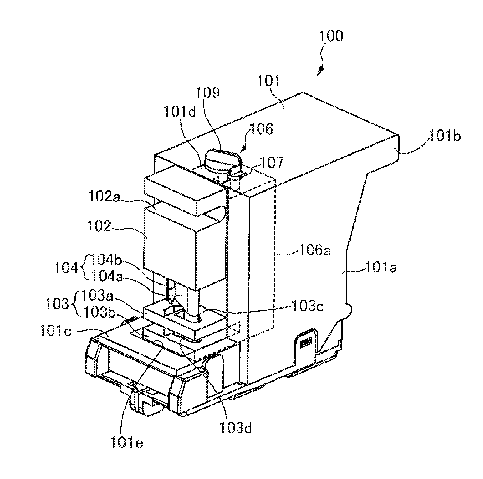
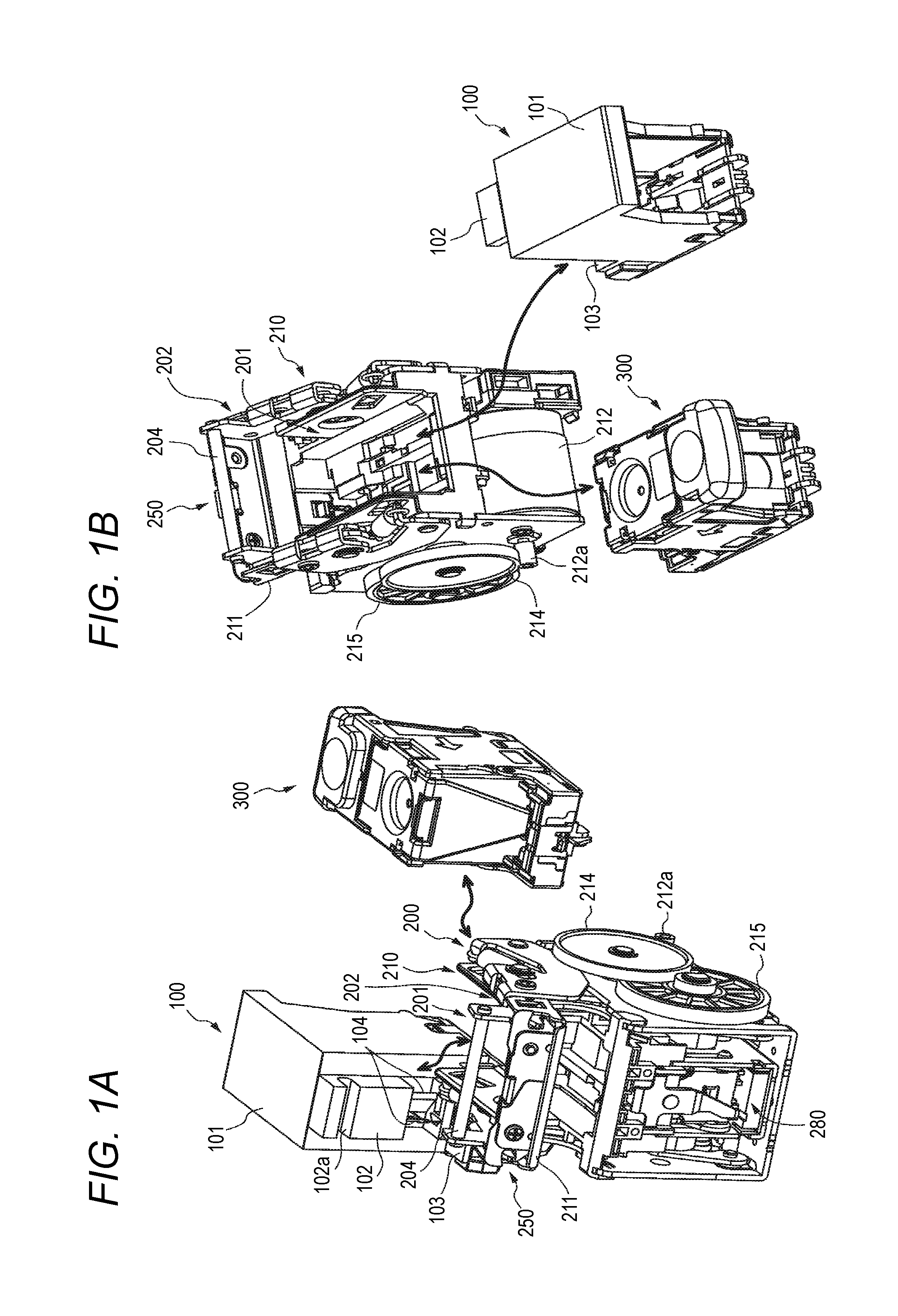
[0077]FIGS. 1A and 1B are perspective views illustrating a binding mechanism cartridge, a binding device body, and a stapler cartridge according to a first embodiment of the present invention. The binding device body 200 is generally installed in a sheet processing apparatus 10 (see FIGS. 24A to 24F) such as a business copier.

[0078]Binding Device

[0079]The binding device body 200 includes a motor 212, various gears 214 and 215 that are rotationally driven by interlocking with the motor 212, a stapler drive mechanism 280 that causes a plate and a driver to move upward and downward, a table moving mechanism 210 that causes a table portion 211 to move upward and downward by interlocking with the upward-and-downward movement of the plate and the driver by the stapler drive mechanism 280, and a clinching mechanism 250 that bends legs of a staple passing through a bundle of paper to the sheet surface of the bundle of sheets. The stapler drive mechanism 280, the table moving mechanism 210, ...

second embodiment

[0168]In the binding mechanism cartridges 100, 120, 140, and 165 according to the first embodiment, the binding process is performed using the table moving mechanism 210 among the drive mechanisms of the binding device body 200. However, the binding process in the binding mechanism cartridge is not limited to the case in which the binding process is performed by interlocking with the table moving mechanism 210, but the binding process may be performed using another moving mechanism unit. In a binding mechanism cartridge according to a second embodiment of the present invention, the binding portion of the upward-and-downward moving portion is brought into pressure contact with a bundle of sheets by interlocking with a clinching operation of the clinching mechanism 250 as well as the table moving mechanism 210.

[0169]Clinching Mechanism of Binding Device Body

[0170]FIG. 13A is a perspective view illustrating a binding device body including a clinching mechanism and a binding mechanism c...

third embodiment

[0183]In the binding mechanism cartridges 100, 120, 140, and 165 according to the first embodiment, the binding process is performed using the table moving mechanism 210 among the drive mechanisms of the binding device body 200. In the binding mechanism cartridge 165 according to the second embodiment, the binding process is performed using the clinching mechanism 250. In a third embodiment of the present invention, a binding mechanism cartridge that performs a binding process using a stapler drive mechanism 280 of the binding device body 200 will be described.

[0184]Stapler Drive Mechanism of Binding Device Body

[0185]FIGS. 15A and 15B and FIGS. 16A to 16D are schematic diagrams illustrating a configuration of the stapler drive mechanism of the binding device body. FIG. 15A illustrates the binding device body and the binding mechanism cartridge using the stapler drive mechanism, FIG. 15B illustrates the internal structure of the binding mechanism cartridge. FIGS. 16A and 16C illustra...


PUM

PropertyMeasurementUnit
Pressureaaaaaaaaaa

Abstract

A binding mechanism cartridge is detachably held by a binding device body instead of a staple cartridge which is detachable into the binding device body. The binding mechanism cartridge includes a body portion, an upward-and-downward moving portion and a base portion. The body portion is detachably held by the binding device body. The upward-and-downward moving portion is on the body portion to move close to or away from one surface of a bundle of sheets by moving upward and downward by interlocking with a drive mechanism of the binding device body. The base portion is on the body portion to face the upward-and-downward moving portion and supports the other surface of the bundle of sheets. The upward-and-downward moving portion includes a binding mechanism which is partially in pressure contact with the one surface according to a movement of the upward-and-downward moving portion to binds the bundle of sheets.

Description

CROSS-REFERENCE TO RELATED APPLICATION[0001]This application is based on and claims priority under 35 USC119 from Japanese Patent Application No. 2014-265478 filed on Dec. 26, 2014.TECHNICAL FIELD[0002]The present invention relates to a binding mechanism cartridge, a binding device body and a sheet processing apparatus, and more particularly, to a binding mechanism cartridge that can be attached to and detached from a binding device body in which a staple cartridge or a stapler drive mechanism is detachably held, a binding device body that detachably holds the binding mechanism cartridge, and a sheet processing apparatus on which the binding device body is mounted.BACKGROUND[0003]In the related art, a binding device body (electric stapler) is known which electrically performs a sheet bundle binding process by causing a staple having a C shape to penetrate a bundle of paper sheets stacked (hereinafter, referred to as a bundle of sheets) (for example, see JP-A-2004-358977). The bindin...

Claims


Application Information

Patent Timeline
IPC IPC(8): B42B5/00B65H37/04
CPCB65H37/04B42B5/00B42B2/06B42B5/02G03G15/6544B65H2301/43828B65H2402/10B65H2402/32B65H2402/40B65H2408/122B65H2601/324B65H2601/326B65H2601/422B65H2801/27G03G2215/00822B65H2402/60B65H2404/62
Inventor KENJO, TATSUYA
Owner MAX CO LTD
Why Eureka
Try Eureka