
System, apparatus, and method for recovering barite from drilling fluid

a barite recovery and drilling fluid technology, applied in the field of drilling operations, can solve the problems of not always conveniently falling within the size range that permits such a relatively large wellbore collapse, and the cost of drilling mud in general, and the addition of solid particles in particular,

Active Publication Date: 2016-06-30
VARCO CANADA ULC
View PDF2 Cites 5 Cited by
  • Summary
  • Abstract
  • Description
  • Claims
  • Application Information

AI Technical Summary

Benefits of technology

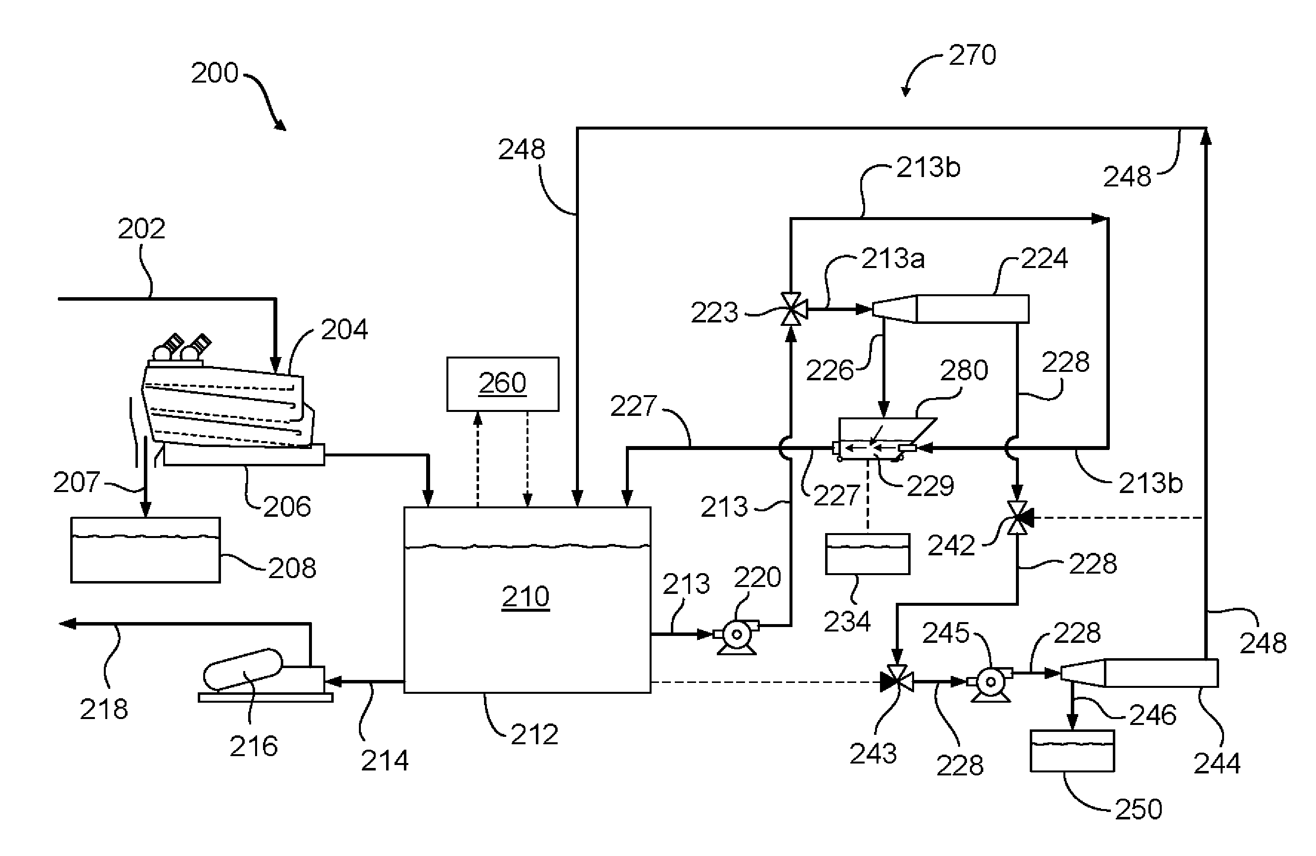
The patent describes new systems, methods, and apparatuses for recovering barite from drilling fluid. One system includes a barite recovery hopper that can collect and mix barite particles with drilling mud. Another system includes a flow redirection apparatus that separates solids particles from drilling mud and directs them back into the mud tank for recycling. The patent also describes a method of using the systems to recover barite from drilling fluid. The technical effects of this patent include improved methods and systems for recovery of barite from drilling fluid, which can reduce costs and increase efficiency.

Problems solved by technology

As would be appreciated by those of ordinary skill, the drilling mud in general, and the added solid particles in particular, can often be very expensive.
However, it should be appreciated that while the sizes of a large majority of the drill cuttings particles enable them to be separated with machines that utilize vibratory screening techniques, such as shale shakers and the like, the sizes of many solids particles do not always conveniently fall within the size range that permits such relatively easy separation, e.g., the 150 micron size threshold noted above.
For example, the presence of drill cuttings particles in the drilling mud mixture may have a significant effect on the weight of the mud, which could potentially lead to wellbore collapse, and / or a blowout scenario associated with possibly hazardous overpressure conditions within the well.
Additionally, the presence of undesirable solids materials in the drilling mud can also have an adverse effect on the flow and / or hydraulic characteristics of the mud, which could thus potentially have a detrimental influence the operational efficiency of the hydraulically driven downhole tools, lubrication and cooling of the drill bit, and the like.
Furthermore, depending on the types of materials (e.g., rocks / minerals) that make up the drill cuttings, the drill cuttings particles can be highly abrasive, and therefore could be damaging to the drilling mud circulation equipment, such as mud pumps, seals, valves, and the like.
In such cases, expensive drilling downtime may be encountered during the repair and / or replacement of inordinately worn or damaged equipment.
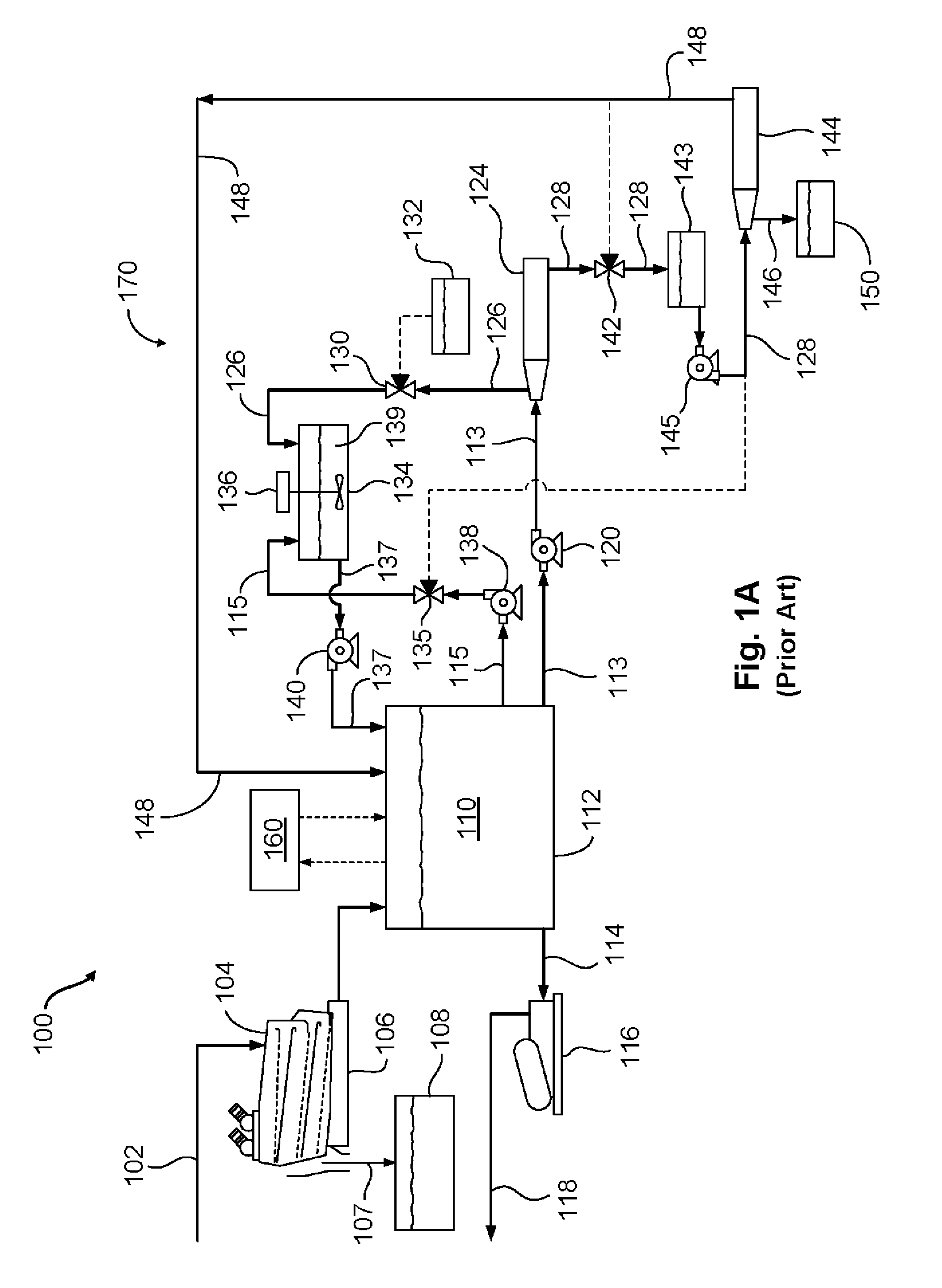
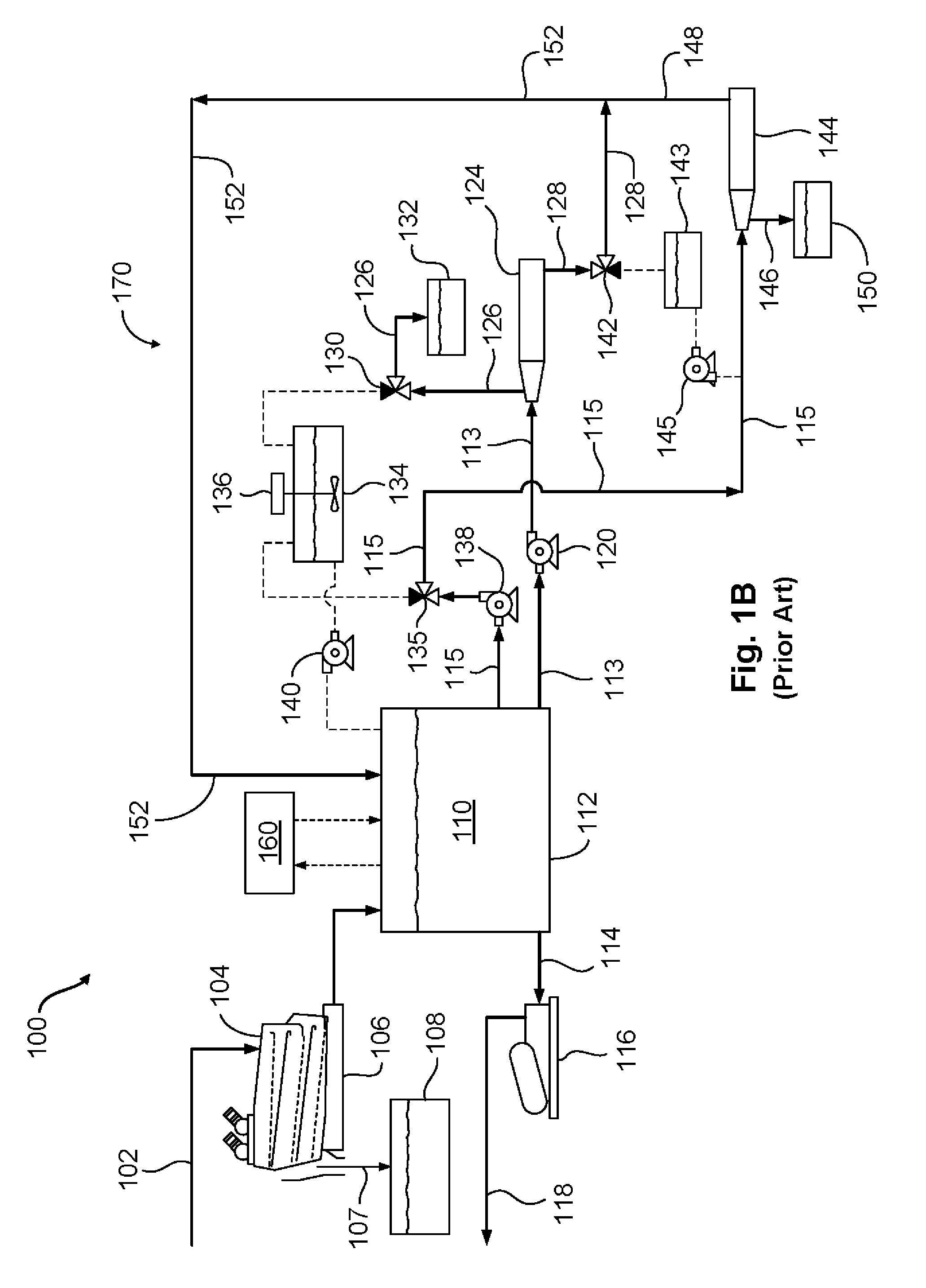
Accordingly, the lower centrifugal force created within the first decanter centrifuge will be sufficient to remove the higher density barite particles, but will be less effective in removing the lower density drill cuttings particles.
However, there are significant capital and operation costs, as well as safety and environment considerations, associated with the fabrication, assembly, and operation of such a prior art barite recovery system.
Additionally, a significant amount of additional piping is required so as to make up the appropriate interconnections between the extra pieces of equipment (tanks, pumps, etc.), all of which can take up a substantial footprint in areas where plot space often comes at a premium.
Moreover, operating the additional tankage, pumping, and plumbing equipment can lead to drilling mud spillage, which brings with it the environmental issues associated with any related cleanup activities, including the disposal of the additional volumes of drilling mud that are required to support the overall barite recover operation.

Method used


Image

  • System, apparatus, and method for recovering barite from drilling fluid
  • System, apparatus, and method for recovering barite from drilling fluid
  • System, apparatus, and method for recovering barite from drilling fluid

Examples


Embodiment Construction

[0042]Various illustrative embodiments of the present subject matter are described below. In the interest of clarity, not all features of an actual implementation are described in this specification. It will of course be appreciated that in the development of any such actual embodiment, numerous implementation-specific decisions must be made to achieve the developers' specific goals, such as compliance with system-related and business-related constraints, which will vary from one implementation to another. Moreover, it will be appreciated that such a development effort might be complex and time-consuming, but would nevertheless be a routine undertaking for those of ordinary skill in the art having the benefit of this disclosure.

[0043]The present subject matter will now be described with reference to the attached figures. Various systems, structures and devices are schematically depicted in the drawings for purposes of explanation only and so as to not obscure the present disclosure ...


PUM

PropertyMeasurementUnit
Flow rateaaaaaaaaaa
Densityaaaaaaaaaa
Specific gravityaaaaaaaaaa

Abstract

A barite recovery hopper includes a shell having an open top, wherein the barite recovery hopper is adapted to receive a flow of recovered barite particles from a solids discharge chute of a decanter centrifuge through the open top of the shell. An inlet is adapted to receive a flow of drilling mud from a mud tank. A hopper bypass gate is adapted to seal a bottom opening of the shell when the hopper bypass gate is in a closed position during a barite recovery operation, and to allow collection of at least a portion of the recovered barite particles for mixture, inside of the barite recovery hopper, with the flow of drilling mud received through the inlet when the hopper bypass gate is in the closed position. An outlet is adapted to discharge a flow of the recovered barite particle / drilling mud mixture to the mud tank.

Description

BACKGROUND[0001]1. Field of the Disclosure[0002]The present subject matter is generally directed to drilling operations, and in particular, to systems, apparatuses, and methods that may be used for recovering high density solids particles such as barite from drilling fluid.[0003]2. Description of the Related Art[0004]During a typical well drilling operation, such as when an oil and gas well is drilled into the earth, a drilling mud circulation and recovery system is generally used to circulate drilling fluid, i.e., drilling mud, into and out of a wellbore. The drilling mud provides many functions and serves many useful purposes during the drilling operation, such as, for example, removing drill cuttings from the well, controlling formation pressures and wellbore stability during drilling, sealing permeable formations, transmitting hydraulic energy to the drilling tools and bit, and cooling, lubricating, and supporting the drill bit and drill assembly during the drilling operations.[...

Claims


Application Information

Patent Timeline
IPC IPC(8): B01D21/02
CPCB01D21/02B01D21/262B01D2221/04E21B21/065
Inventor ZAZULA, RENNIE K.BIRD, DEAN M.CROSSWHITE, DONALD T.
Owner VARCO CANADA ULC
Learn More