
Depth sensing method, device and system based on symbols array plane structured light

Active Publication Date: 2016-06-23
NINGBO YINGXIN INFORMATION TECH
View PDF14 Cites 15 Cited by
  • Summary
  • Abstract
  • Description
  • Claims
  • Application Information

AI Technical Summary

Benefits of technology

The present invention is a technology that can quickly and accurately obtain high-resolution depth information from a dynamic scene. This technology can be easily integrated into different hardware platforms and operating systems, making it ideal for use in smart devices such as smart phones and tablets. With this invention, devices can achieve real-time 3D scanning, modeling, and mapping. The patent also describes a depth sensing device for symbols array plane structured light, which is a specific embodiment of the invention.

Problems solved by technology

However, Kinect uses DoE diffraction to generate the laser speckle image, which is difficult to obtain high-resolution and high-precision depth information and difficult to meet the needs of applications in industrial modeling field, etc., and has unavailable ability to self-correcting the improper depth values or holes.
At the same time, the existing technologies of structured light encoding depth sensing and 3D measurement are difficult to acquire real-time high-resolution and high-precision depth information of the target object in the dynamic scene.

Method used


Image

  • Depth sensing method, device and system based on symbols array plane structured light
  • Depth sensing method, device and system based on symbols array plane structured light
  • Depth sensing method, device and system based on symbols array plane structured light

Examples


Embodiment Construction

[0034]The present invention will be described in further detail in combination with the drawings.

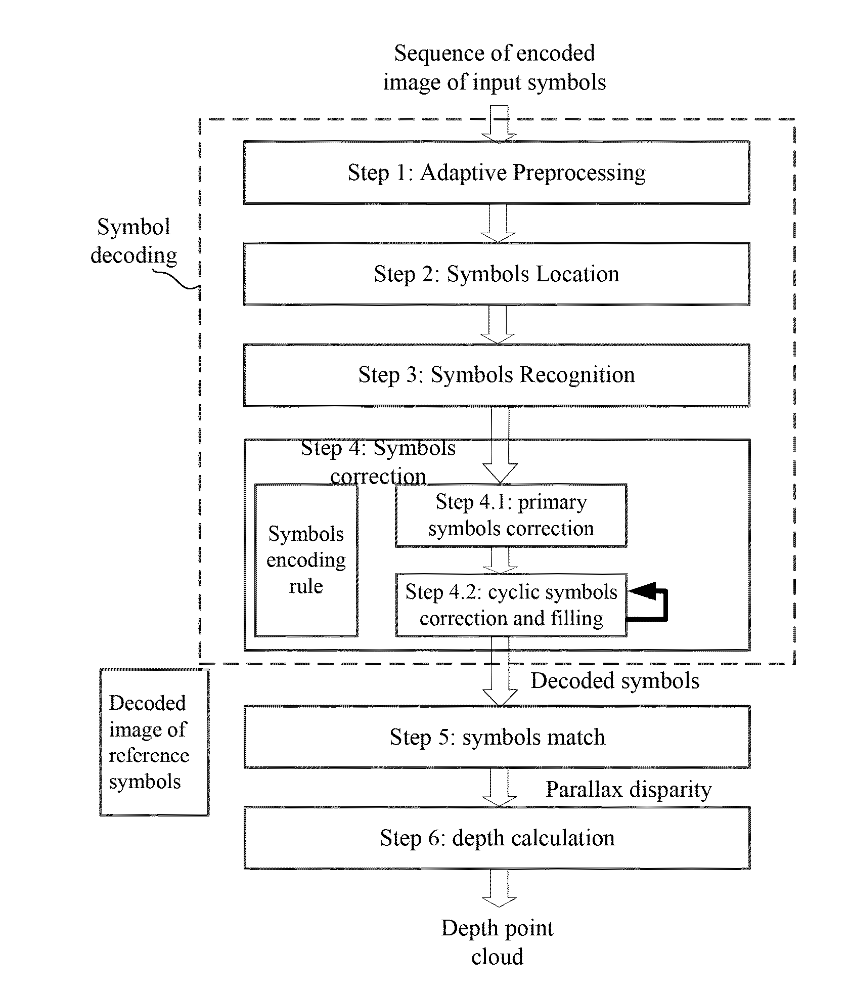
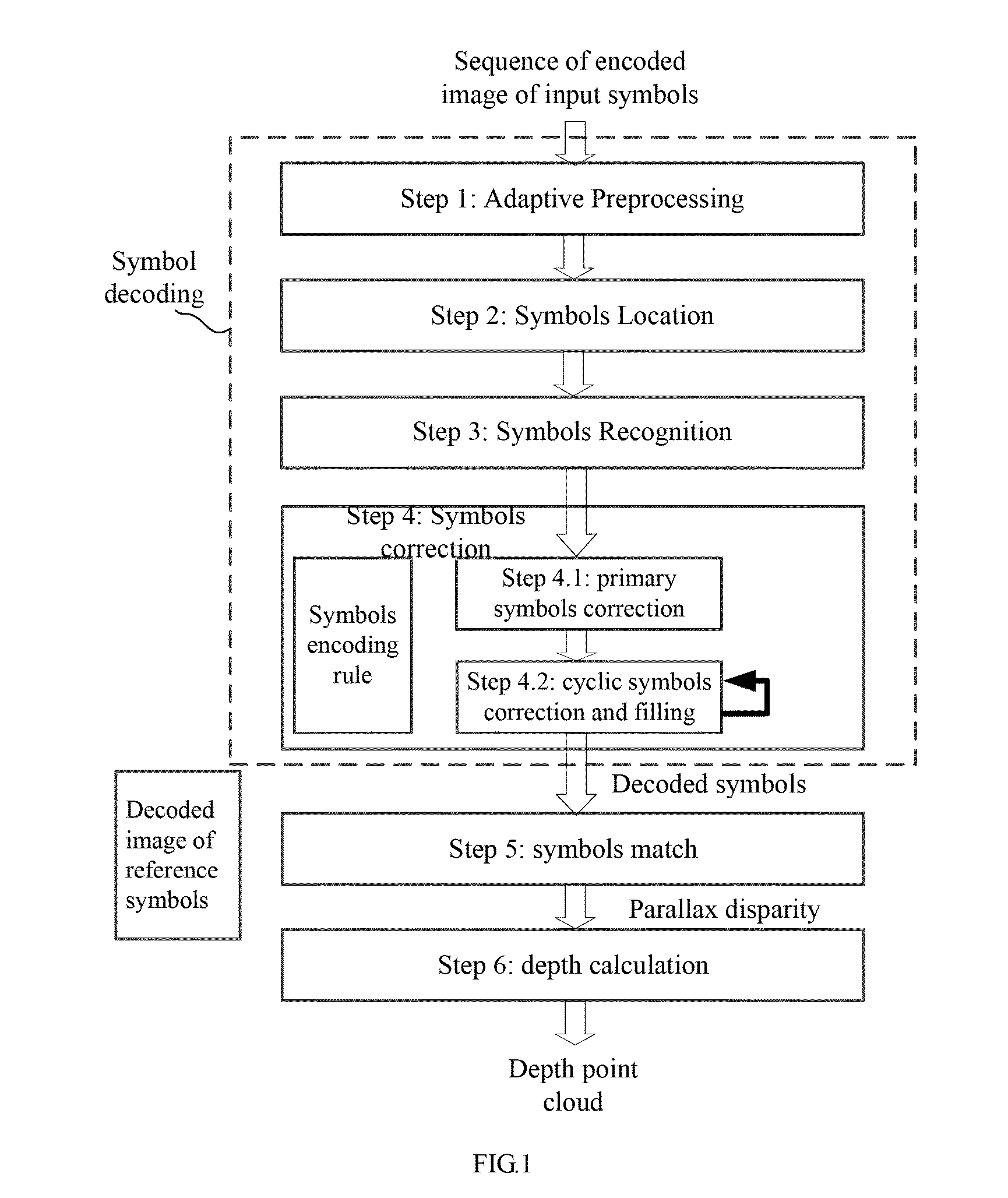
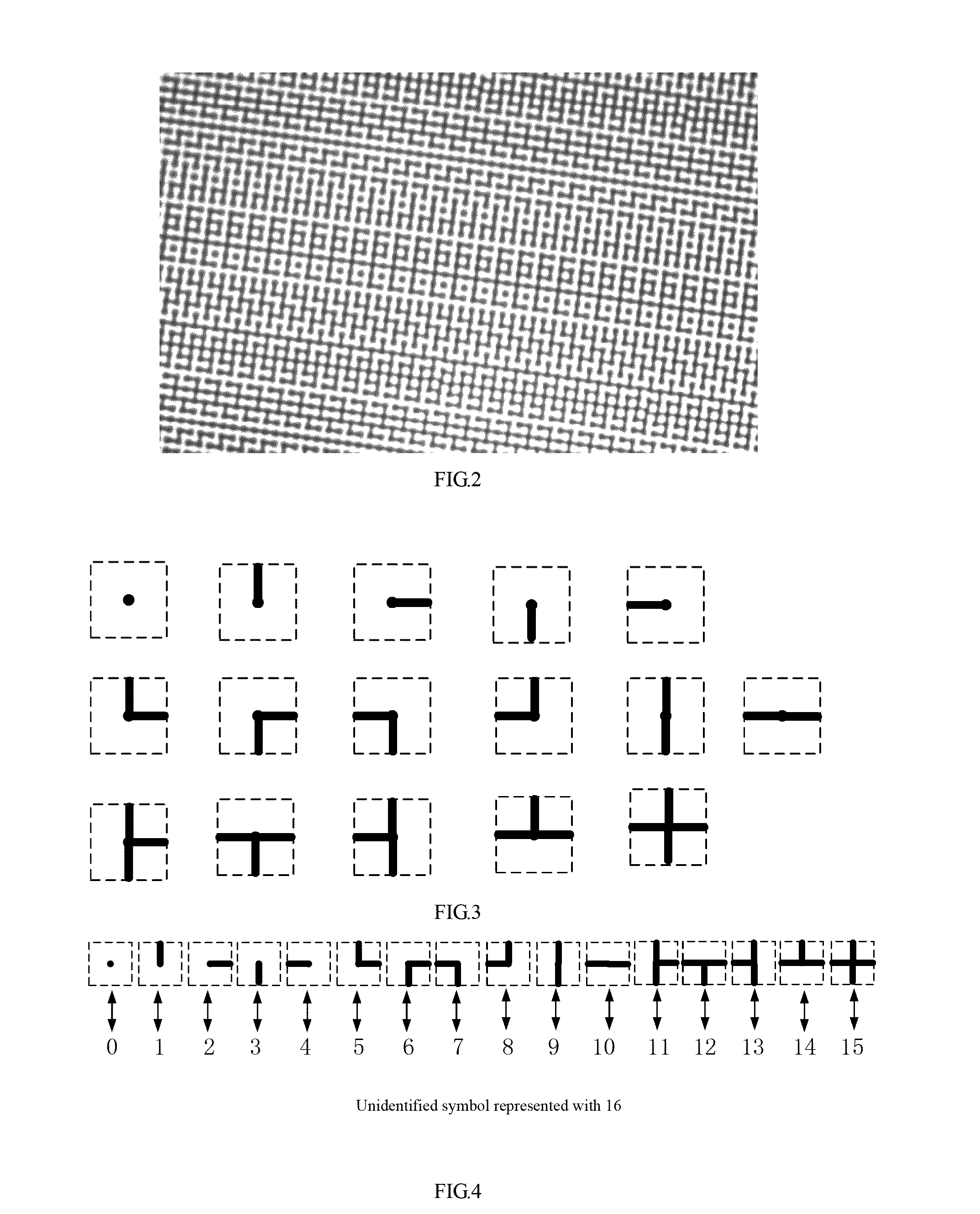
[0035]FIG. 1 schematically illustrates a overall flow chart of a depth sensing of symbols array plane structured light according to an embodiment of the present invention. For clarity, the method will be described hereinafter in combination with FIG. 2, FIG. 3, FIG. 4, FIG. 5, FIG. 6, FIG. 7, FIG. 8, FIG. 9 and FIG. 10

[0036]The laser pattern projector is a projecting device of laser encoded graphical pattern, the projected pattern may be fixed or can be changed programmatically; the projection can be in the synchronized control with the reception by the image sensor; the projected patterns have a certain horizontal and vertical viewing angle FoV; the laser light source may be visible light, infrared light, ultraviolet or X-ray.

[0037]The code symbols refer to symbols that are regular and have the same size, such as numbers, letters and symbols with specific shapes. The code symbols can be...


PUM


Abstract

The present invention discloses a depth sensing method, device and system based on symbols array plane structured light. The coded symbols array pattern is projected by the laser pattern projector to the target object or space, and the image sensor collects and obtains the successive sequence of the encoded image of the input symbols. Firstly, the input image encoded with the symbols is decoded. The decoding process includes preprocessing, symbols location, symbols recognition and symbols correction. Secondly, the disparity of the decoded symbols are calculated by the symbols match calculation between the decoded image of the input symbols with completed symbols recognition and the decoded image of the reference symbols with the known distance. Finally the depth calculation formula is combined to generate depth point cloud information of the target object or projection space that is represented in the form of grid. The present invention can quickly obtain high-resolution and high-precision depth information of the target object or projection space in dynamic scenes, which facilitates the porting or insertion as a module into the intelligent device for 3D modeling, 3D mapping, etc.

Description

FILED OF THE INVENTION[0001]The present invention belongs to the technical fields of pattern recognition, human-computer interaction, 3D reconstruction and machine vision technology. More specifically, it relates to a depth sensing method, device and system based on symbols array plane structured light.BACKGROUND OF THE INVENTION[0002]In the field of consumer electronics, depth sensing technology helps to improve the intelligence level and interaction ability of electronic products and helps intelligent terminals to understand human actions, so that it has become one of the interactive tools between the “real physical world” and the “virtual network world”, which could not only realize innovative applications in the fields of smart TV, smart phones, home appliances, tablet PC, etc., but also be used in intelligent video monitoring, facial identification system, 3D animation, dynamic scene detection and 3D reconstruction such as real-time 3D mapping. In industrial field, there is a w...

Claims


Application Information

Patent Timeline
IPC IPC(8): G01B11/22G06K9/52G06T7/00H04N19/44G01B11/25G06K9/62G06V10/145
CPCG01B11/22G01B11/254G06K9/6201G06K9/52H04N19/44G06K9/6267G06T7/0051H04N19/597G06T7/521H04N13/254G06V10/145G06V10/7515G01B11/25G01B11/00A61B5/0062G06T7/50G01B11/26G06T2207/10028A61B5/1077G01S17/06G06T7/593G01B11/2513G01B11/2518
Inventor GE, CHENYANGZHOU, YANHUI
Owner NINGBO YINGXIN INFORMATION TECH
Learn More