
Method for controlling an engine braking device and engine braking device

Active Publication Date: 2016-06-16
MAN TRUCK & BUS OESTERR
View PDF11 Cites 3 Cited by
  • Summary
  • Abstract
  • Description
  • Claims
  • Application Information

AI Technical Summary

Benefits of technology

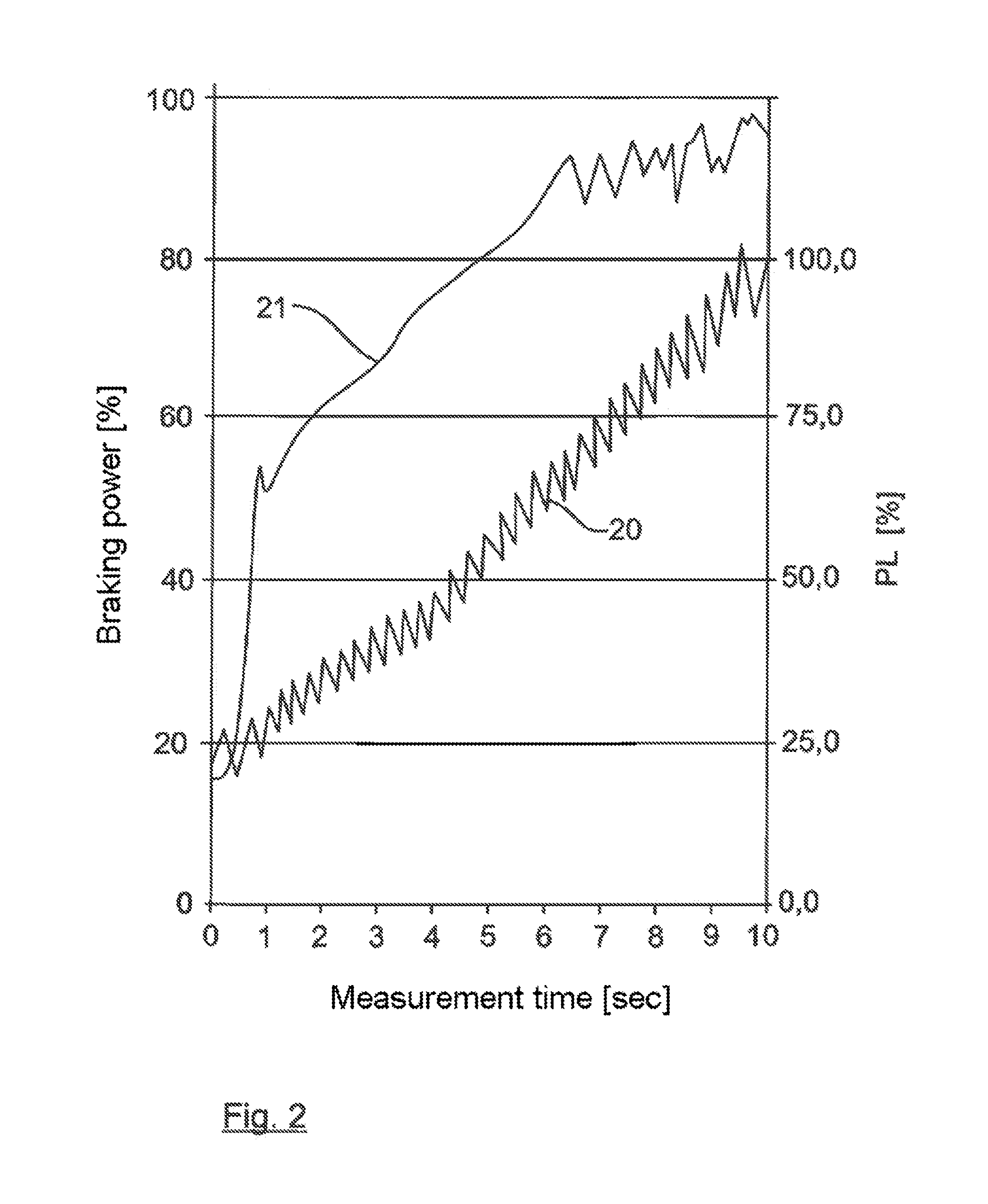
The invention provides a method and device for increasing the engine braking power of a combustion engine by injecting fuel into the combustion chamber during engine braking. This increases the boost pressure in the intake system, leading to increased braking power and greater heat dissipation in the engine. The method also causes a gradual increase in the engine braking power over time due to the progressive rise in exhaust gas energy. This invention improves the performance and efficiency of engine braking in vehicles.

Problems solved by technology

On the one hand, this causes the increase in braking power, in particular by the decompression brake used, and, on the other hand, leads to greater heat dissipation in the combustion engine via the exhaust system.

Method used


Image

  • Method for controlling an engine braking device and engine braking device
  • Method for controlling an engine braking device and engine braking device
  • Method for controlling an engine braking device and engine braking device

Examples


Embodiment Construction

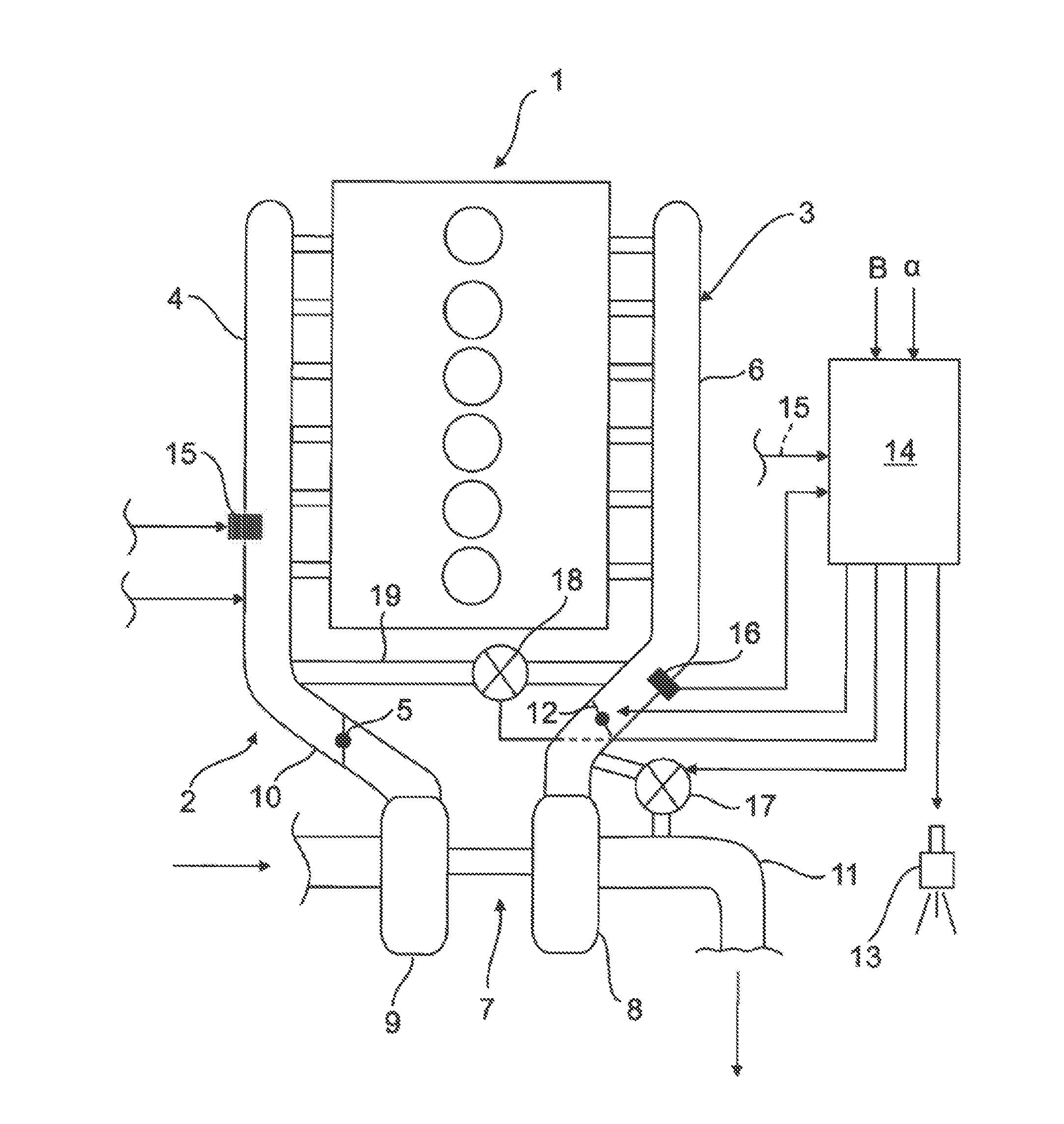
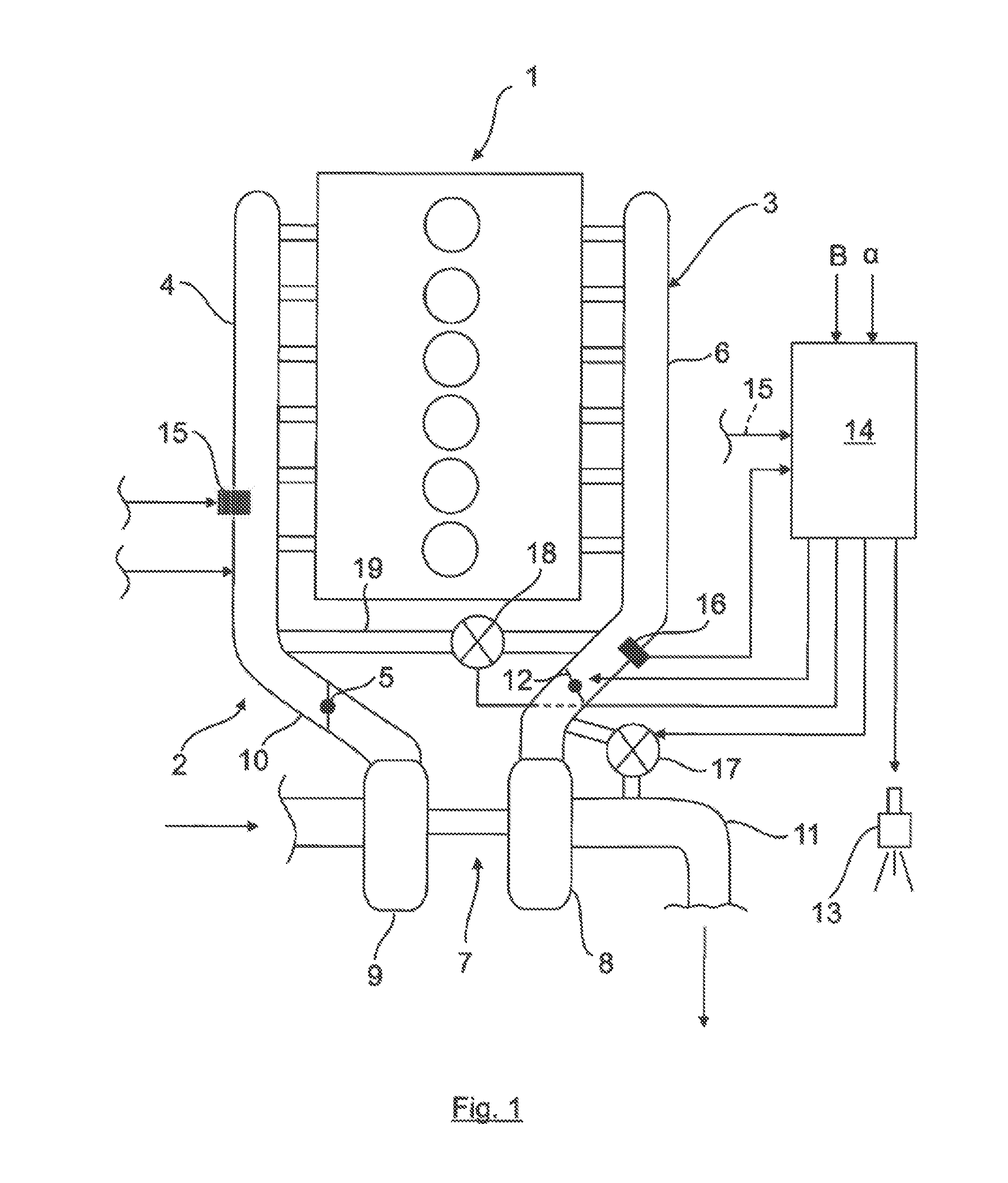
[0027]A combustion engine 1 (e.g., a six-cylinder diesel combustion engine) for a motor vehicle, in particular for a commercial vehicle, having an intake system 2 and an exhaust system 3 (of conventional construction where not described) is shown in a purely schematic way in FIG. 1. A throttle valve 5 can optionally be provided in the intake manifold 4 of the intake system 2.

[0028]The exhaust system 3 has an exhaust manifold 6, which is connected to the combustion chambers of the combustion engine 1 and is connected directly or indirectly to the exhaust turbine 8 of an exhaust turbocharger 7. The exhaust turbine 8 drives a compressor 9 in a known manner, the compressor being connected, in turn, to the intake manifold 4 by a line 10 and delivering combustion air at a defined boost pressure PL to the combustion chambers of the combustion engine 1. The exhaust gas flowing out via the exhaust manifold 6 and the exhaust turbine 8 is carried away further by an exhaust line 11. The other l...


PUM


Abstract

The invention relates to a method for controlling an engine braking device for a combustion engine in motor vehicles, in particular in commercial vehicles, which has an intake system, an exhaust system, gas exchange valves associated with the combustion engine, a fuel injection device, which injects fuel into at least one combustion chamber, an exhaust turbocharger integrated into the exhaust system and the intake system, and an engine braking unit, wherein the engine braking unit has a decompression brake, which influences at least one outlet valve of the gas exchange valves, and a brake flap, which is arranged in the exhaust system and causes the exhaust gas to build up. According to the invention, as engine braking starts or during engine braking, fuel is injected into at least one combustion chamber of the combustion engine for a predefined period of time.

Description

CROSS-REFERENCE TO RELATED APPLICATIONS[0001]The present application claims priority of A 909 / 2014 filed Dec. 15, 2014, which is incorporated herein by reference.BACKGROUND OF THE INVENTION[0002]The present invention relates to a method for controlling an engine braking device for a combustion engine in motor vehicles, in particular in commercial vehicles, to an engine braking device and to a vehicle having the engine braking device.[0003]In air-compressing (diesel) combustion engines in commercial vehicles, there is a known practice of producing an exhaust gas backpressure in the exhaust system using a brake flap in the overrun mode, the backpressure bringing about effective engine braking since the pistons of the combustion engine operate against this exhaust gas pressure during the exhaust stroke (outlet valves open).[0004]In order significantly to increase the effect of such an engine braking device, there is a practice, known from U.S. Pat. No. 5,150,678 for example, of additio...

Claims


Application Information

Patent Timeline
IPC IPC(8): F02D13/04F01L13/06
CPCF01L13/06F02D13/04F02B37/12F02D9/06F02D41/40F02D41/04F02D41/38F02B33/44
Inventor RAMMER, FRANZKREUZRIEGLER, ANDRE
Owner MAN TRUCK & BUS OESTERR
Learn More