
Devices and Methods for Creating a Predictable Capsulorhexis of Specific Diameter

a capsulorhexis and specific diameter technology, applied in the field of cataract surgery, can solve the problems of radial tear complication, potentially blinding complications, difficulty in controlling the cutting tip path of the device, etc., and achieve the effect of facilitating the movement of the devi

Active Publication Date: 2016-06-16
UNIV OF COLORADO THE REGENTS OF
View PDF8 Cites 25 Cited by
  • Summary
  • Abstract
  • Description
  • Claims
  • Application Information

AI Technical Summary

Benefits of technology

The invention is a device and method for performing a capsulorhexis, which is a surgical procedure used to treat eye conditions. The device has a ring with positioning holes that allow it to be positioned accurately over the eye's lens capsule, where the capsulorhexis is to be performed. The device is inserted into the eye through a small incision and positioned to cut the capsule. The technical effect of the device is to simplify the procedure of capsulorhexis, making it safer and easier for ophthalmic surgeons to perform.

Problems solved by technology

Such a radial tear constitutes a complication since it destabilizes the lens for further cataract removal and safe intraocular lens placement within the lens capsule later in the operation.
Importantly, these complications are potentially blinding.
This is due to the extreme difficulty in controlling the path of the cutting tip of the device.
Either of these approaches involves a very challenging maneuver and the tearing motion can sometimes lead to an undesirable tear of the capsule toward the back of the lens (i.e. toward the posterior capsule), even in the most experienced hands.
Moreover, even if a smooth capsular opening without tags is ultimately produced, the size and / or position of the capsular opening may present a problem.
For instance, a capsular opening that is too small can impede the safe removal of the lens nucleus and cortex and prevent proper intraocular lens insertion into the lens capsule.
The additional stresses necessary to accomplish the operation with a small or misplaced capsular opening put the eye at risk for zonular and capsular breakage.
Either of these complications will likely increase the length and complexity of the operation and may result in vitreous loss.

Method used


Image

  • Devices and Methods for Creating a Predictable Capsulorhexis of Specific Diameter
  • Devices and Methods for Creating a Predictable Capsulorhexis of Specific Diameter
  • Devices and Methods for Creating a Predictable Capsulorhexis of Specific Diameter

Examples


embodiment 1

Nitinol Knife

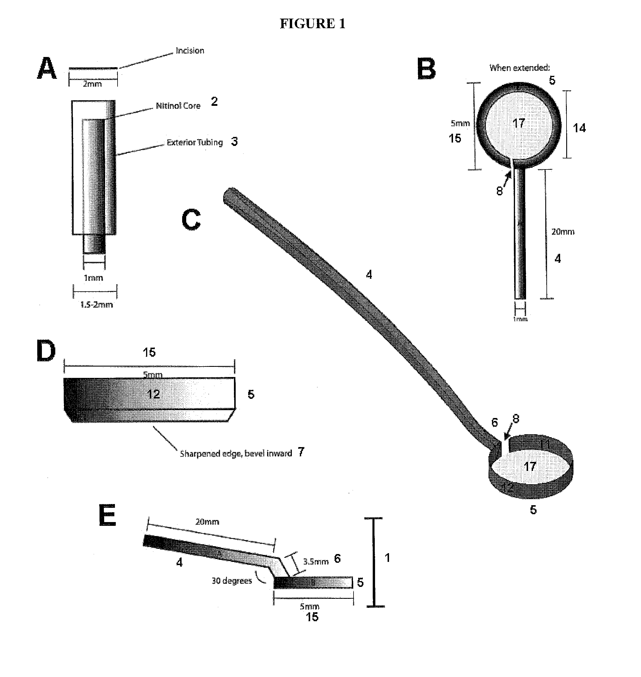
[0110]Initially, a flexible circular nitinol blade was designed that could be inserted into the anterior chamber through a cannula. Nitinol is a 1:1 nickel:titanium alloy most common used for expandable stents. The alloy has both shape memory and superelastic properties. The design took advantage of the alloy's superelasticity. The device was designed so that the blade would be retracted into a cannula, which would then be inserted into a corneal incision. The nitinol blade would then be deployed inside the anterior chamber, where it would reassume its circular shape. The blade would then be used to cut the capsule in “cookie cutter” fashion. A contract manufacturer supplied the nitinol prototypes based on computer-aided design (CAD) files provided, and the bottom edge was sharpened with a drummel. See FIG. 1 for original design.

[0111]The nitinol blade was tested in a bovine ex vivo environment. Because of difficulty with minimally invasive insertion of the blade into t...

embodiment 2

Nitinol Guide Wire

[0112]The results of the first embodiment caused a reconsideration of the strategy of a cutting device. The strategy was changed to guiding a manual capsulorhexis inside a circular device 19. A guide wire 21 was designed, again made from nitinol. Deployment through the incision was similar to the first device 1; the wire 21 was drawn into a cannula 20, inserted into a corneal incision, and then deployed in the anterior chamber, see FIG. 3. The wire 21 rested on top of the capsule, allowing for guidance of a manual capsulorhexis using standard techniques with an Utrata forceps. Prototypes were made by a contract manufacturer based on CAD's provided. There was difficulty inserting the device 19 through a corneal incision due to the curving of the alloy as it entered into the anterior chamber. The prototypes were tested in a bovine ex vivo eye open-sky environment. In each experiment, the guide wire sat flush on the capsule, and guided the rhexis to some degree for on...

embodiment 3

Flexible Suction Ring

[0113]This embodiment maintained the concept of CCC guidance, but moved away from nitinol as a material, as well as the use of manual downward pressure as a method of adherence to the capsule. It was felt that the downward pressure used in the previous embodiments was not optimum. Instead, a flexible polymeric device capable of producing suction against the capsule was designed, which theoretically would provide adequate adhesion in order to guide a CCC, see FIG. 5. The prototype was again made by a contract manufacturer based on the furnished CAD's. The device was first tested in ex vivo bovine eyes. The device was folded and insertion through a 2.4 millimeter incision was attempted but it was deemed too small for atraumatic entry, and so an open sky technique was adopted. The device was placed on top of the capsule, and suction was generated using a 27-guage needle attached to an extension of the ring prototype. Unfortunately none of the devices tested provide...


PUM


Abstract

The present invention relates generally to the field of cataract surgery and more particularly to methods and apparatus for performing a capsulorhexis. This invention is in the field of medical devices. The present invention relates to a device constructed from metals, polymers or other materials that are amenable to precise surface modifications and methods for its use, wherein (1) the device assists in capsulorhexis and (2) a patterned surface having milli-, micron-, and / or nano-sized micropatterning characteristics that imparts surface stabilizing and self-adhesive properties.

Description

CROSS-REFERENCE TO RELATED APPLICATIONS[0001]The present application claims the benefit of U.S. Provisional Patent Application No. 61 / 829,727, filed on. May 31, 2013, which is incorporated herein by reference.FIELD OF THE INVENTION[0002]The present invention relates generally to the field of cataract surgery and more particularly to methods and apparatus for performing a capsulorhexis. This invention is in the field of medical devices. The present invention relates to a device constructed from metals, polymers or other materials that are amenable to precise surface modifications and methods for its use, wherein (1) the device assists in capsulorhexis and (2) a patterned surface having micron-, and / or nano-sized patterning characteristics imparts surface stabilizing and self-adhesive properties.BACKGROUND OF THE INVENTION[0003]An accepted intervention for the treatment of cataracts is surgical removal of the lens and replacement of the lens function by an artificial intraocular lens ...

Claims


Application Information

Patent Timeline
IPC IPC(8): A61F9/007
CPCA61F9/00754A61F9/007
Inventor KAHOOK, MALIK Y.POWERS, MATTHEW ARMSTRONG
Owner UNIV OF COLORADO THE REGENTS OF
Learn More