
Method and Apparatus for Detecting Neural Injury

a neural injury and neural injury technology, applied in the field of neural injury detection methods and apparatuses, can solve the problems of paralysis, weakness or chronic pain, and post-operative damage can also occur, and the pressure applied to the spinal cord during surgery while the patient is under general anesthetic can have serious and long-lasting effects and may not be noticed

Inactive Publication Date: 2016-06-16
SALUDA MEDICAL PTY LTD
View PDF3 Cites 60 Cited by
  • Summary
  • Abstract
  • Description
  • Claims
  • Application Information

AI Technical Summary

Benefits of technology

The present invention recognizes that measuring the compound action potential can help monitor for damage to the nervous system over time and can provide a quick diagnostic to detect the onset of neural injury. Different modes of injury affect the electrical activity of the nervous system in different ways, so the invention can track multiple indicators to better determine the type of injury and allow for faster diagnosis and treatment. This could prevent permanent damage to the nervous system and improve the chances of recovery.

Problems solved by technology

Complications of implanting a surgical lead can include damage to the spinal cord due to direct pressure of the lead as it is placed into the epidural space, cerebrospinal fluid (CSF) leakage, damage to the dorsal roots, and infection of the battery or electrode site, any of which can cause paralysis, weakness, or chronic pain.
Post-operative damage can also occur due to the development of a hematoma over the lead which then creates pressure on the lead and damages the dorsal column axons, or due to electrical stimulation at an excessive current amplitude and / or frequency.
Although such intraoperative and postoperative complications are not common, they can be very serious.
Pressure applied to the spinal cord during surgery while the patient is under general anesthetic can have serious and long lasting effects and may not be noticed until after a procedure.

Method used


Image

  • Method and Apparatus for Detecting Neural Injury
  • Method and Apparatus for Detecting Neural Injury
  • Method and Apparatus for Detecting Neural Injury

Examples


Embodiment Construction

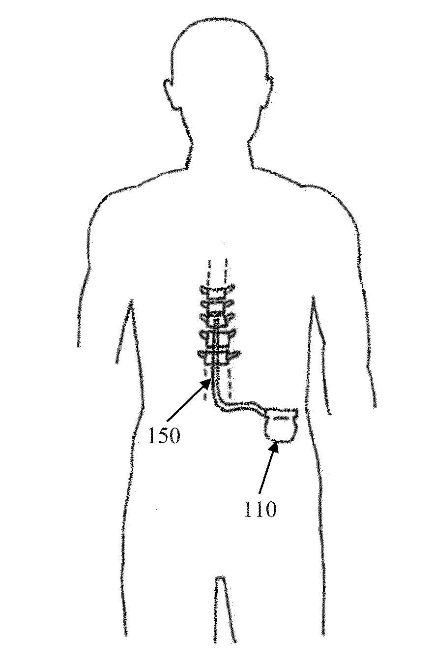
[0052]FIG. 1 schematically illustrates an implanted spinal cord stimulator 100. Stimulator 100 comprises an electronics module 110 implanted at a suitable location in the patient's lower abdominal area or posterior superior gluteal region, and an electrode assembly 150 implanted within the epidural space and connected to the module 110 by a suitable lead.

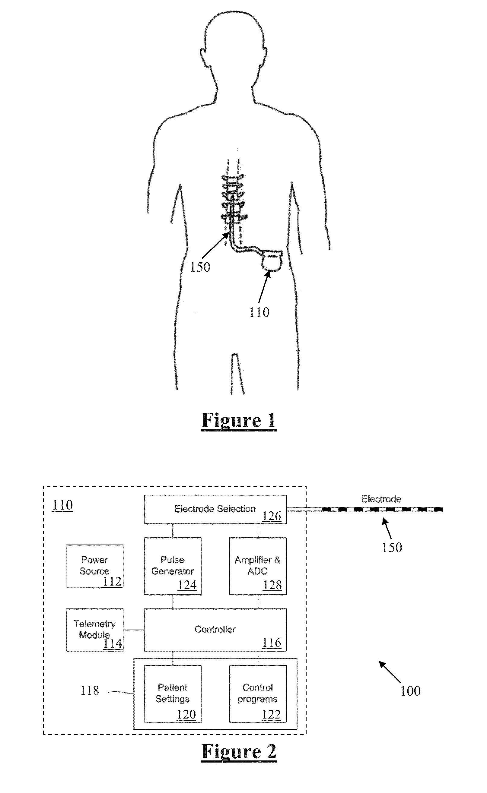
[0053]FIG. 2 is a block diagram of the implanted neurostimulator 100. Module 110 contains a battery 112 and a telemetry module 114. In embodiments of the present invention, any suitable type of transcutaneous communication, such as infrared (IR), electromagnetic, capacitive and inductive transfer, may be used by telemetry module 114 to transfer power and / or data between an external device and the electronics module 110.

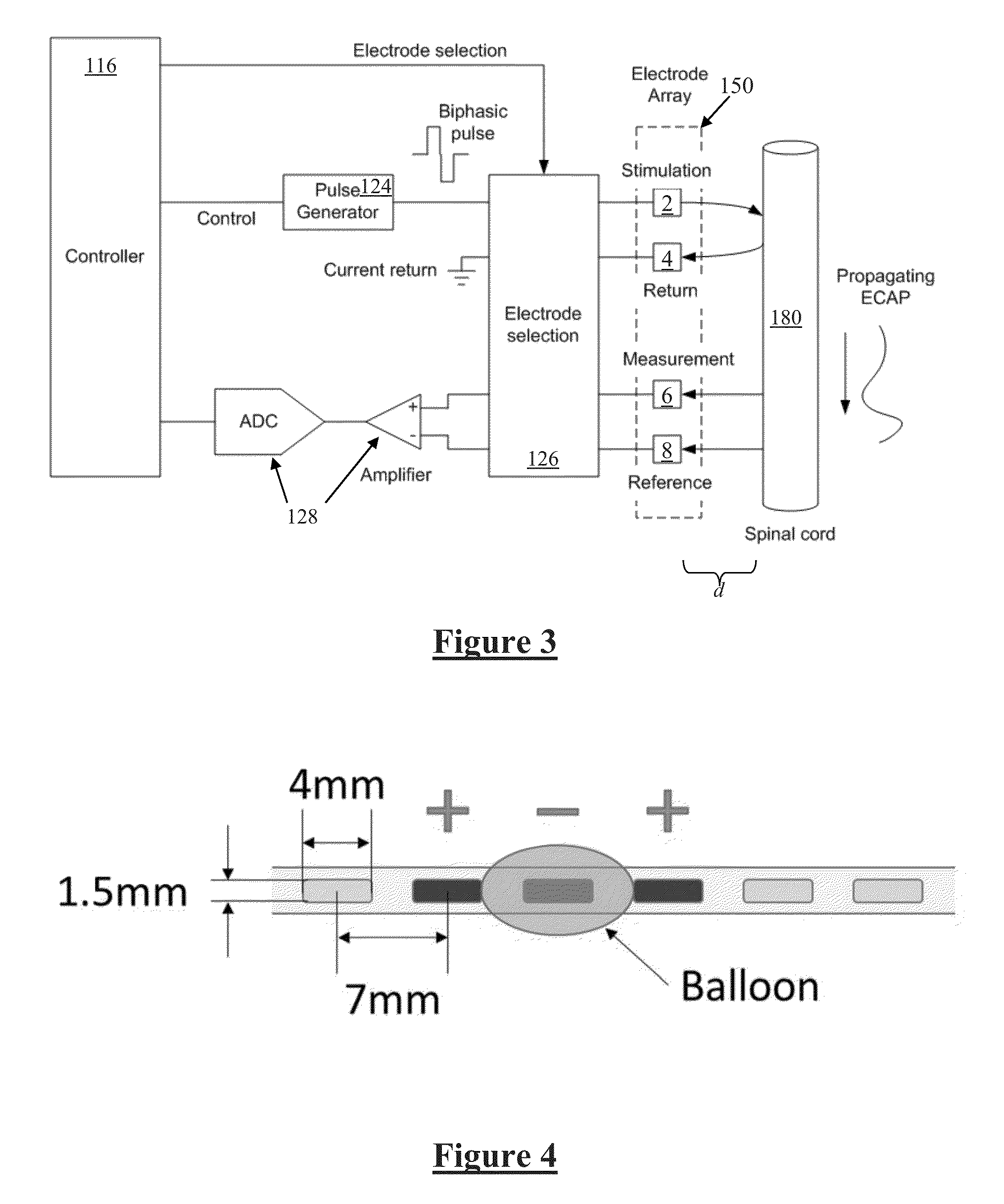
[0054]Module controller 116 has an associated memory 118 storing patient settings 120, control programs 122 and the like. Controller 116 controls a pulse generator 124 to generate stimuli in the form of current pulses...


PUM


Abstract

An implantable device for monitoring for neural injury has a plurality of electrodes including stimulus electrodes and sense electrodes. A stimulus source provides a stimulus to be delivered to a nerve in order to give rise to an evoked action potential. Measurement circuitry records a neural compound action potential signal sensed at the sense electrodes. A stream of control stimuli are applied to the nerve over time and the evoked neural responses are measured. A diagnostic parameter of the measured neural responses is monitored over time, in order to detect a change in the diagnostic parameter. If a change in the diagnostic parameter occurs over time, an indication is output that neural injury has occurred.

Description

TECHNICAL FIELD[0001]The present invention relates to monitoring compound action potentials during surgery to assist with implantable electrode placement, and / or to monitoring compound action potentials post surgery to monitor for neural damage and / or onset of neural trauma.BACKGROUND OF THE INVENTION[0002]There are a range of situations in which it is desirable to apply neural stimuli in order to give rise to a compound action potential (CAP). For example, neuromodulation is used to treat a variety of disorders including chronic pain, Parkinson's disease, and migraine. A neuromodulation system applies an electrical pulse to tissue in order to generate a therapeutic effect. When used to relieve chronic pain, the electrical pulse is applied to the dorsal column (DC) of the spinal cord. Such a system typically comprises an implanted electrical pulse generator, and a power source such as a battery that may be rechargeable by transcutaneous inductive transfer. An electrode array is conn...

Claims


Application Information

Patent Timeline
IPC IPC(8): A61B5/04A61B5/00
CPCA61B5/04001A61B5/7282A61B5/407A61B5/686A61B5/4836A61N1/0551A61N1/3605A61B5/24A61N1/00
Inventor OBRADOVIC, MILANCAMERON, TRACYGORMAN, ROBERT BRUCESHARIATI, NASTARAN HESAMPARKER, JOHN LOUIS
Owner SALUDA MEDICAL PTY LTD
Learn More