
System and Method for Renewable Fuel Using Sealed Reaction Chambers

a technology of reaction chamber and renewable fuel, which is applied in the direction of biofuels, chemistry apparatus and processes, and combustible gas coke oven heating. it can solve the problems of difficult to achieve uniform pressure and temperature, difficult to further process to make renewable fuel, and complex process. it achieves the effect of improving biomass processing uniformity and increasing biomass production rates

Inactive Publication Date: 2016-06-09
STRIMLING JON
View PDF0 Cites 11 Cited by
  • Summary
  • Abstract
  • Description
  • Claims
  • Application Information

AI Technical Summary

Benefits of technology

The system and method described in this patent allow for faster and more efficient processing of biomass to separate specific volatile components. This is achieved by using sealed reaction chambers and cartridges that can be transferred between processing stations while maintaining the fluid environment around the biomass. An agitator is also used to mix the biomass and improve processing consistency. The higher production rates of processing biomass or other feedstocks can result in lower costs of equipment per unit of renewable fuel produced. The invention also uses piston assemblies for better sealing and more reliable mechanical reliability, as well as valved ports for controlled fluid flow during transfer between processing stations. The cartridge as a whole can be indexed between processing stations in a sealed configuration, eliminating further sealing and working fluid control issues.

Problems solved by technology

These state-of-the-art methods specifically referenced above overcame a significant challenge of traditional pyrolysis, which had been that in heating biomass in large batches over broad ranges of temperatures, a wide variety of gaseous and liquid compounds were produced in forms that were of mixed composition, and were therefore difficult to further process to make renewable fuels.
This process had been further complicated by the thousands of compounds in biomass feedstock, by the fact that the products of pyrolysis are often not thermodynamically stable, and by the fact that it had been difficult to consistently maintain narrow ranges of pressure and temperature in three dimensional commercial pyrolysis systems.
However, because the biomass layer must be limited to a thin layer for uniformity of heating, scaling up production quantities is more challenging that it would be for larger batches of material, and therefore requires larger, more expensive equipment and / or additional production lines.
Furthermore, because state-of-the-art methods and systems typically heat only surface of the biomass layer and the compressed nature of the biomass layer limits exposed surface area, heating and cooling remains non-uniform despite the aforementioned thickness limitations.
Another drawback of state-of-the-art methodology is that the reduced surface area created by compressing the biomass into a thin layer also decreases the surface to volume ratio, and therefore increases the time required to first heat, second produce the desired reaction products, and third diffuse the reaction products back into the fluidic environment.
Such designs have been commonly employed in small scale experimental uses, but are challenging to scale up for high volume processing.
Additionally, these bellows designs typically have flexible seals which are susceptible to failure on repetitive cycling, so while they are appropriate for short term experimental use, they present reliability challenges at a commercial production scale.
This is particularly true in an environment with supercritical fluids or volatile organic chemicals circulating, which may damage the flexible members, and is also especially true with high pressure differentials between stations, which increase the stresses on the joints in a bellows assembly.
Further complications arise in state-of-the-art methodology when moving materials from one high pressure environment to the next, as from station to station during processing.
The incorporation of such airlocks further increases cost and decreases the mechanical reliability of equipment used to execute state-of-the-art methods.
Additionally, the mixing action itself may continue to break down and pulverize the biomass materials, in particular breaking down the largest particles which might otherwise not effectively volatilize compounds at their core.
The seals in prior tray systems were maintained by flexible bellows sealing to the top of the trays, which can be problematic from the standpoint of mechanical reliability, particularly in an environment with volatile organic chemicals circulating supercritical fluids and high pressure differentials.

Method used


Image

  • System and Method for Renewable Fuel Using Sealed Reaction Chambers
  • System and Method for Renewable Fuel Using Sealed Reaction Chambers
  • System and Method for Renewable Fuel Using Sealed Reaction Chambers

Examples


Embodiment Construction

[0039]Cartridge Embodiments

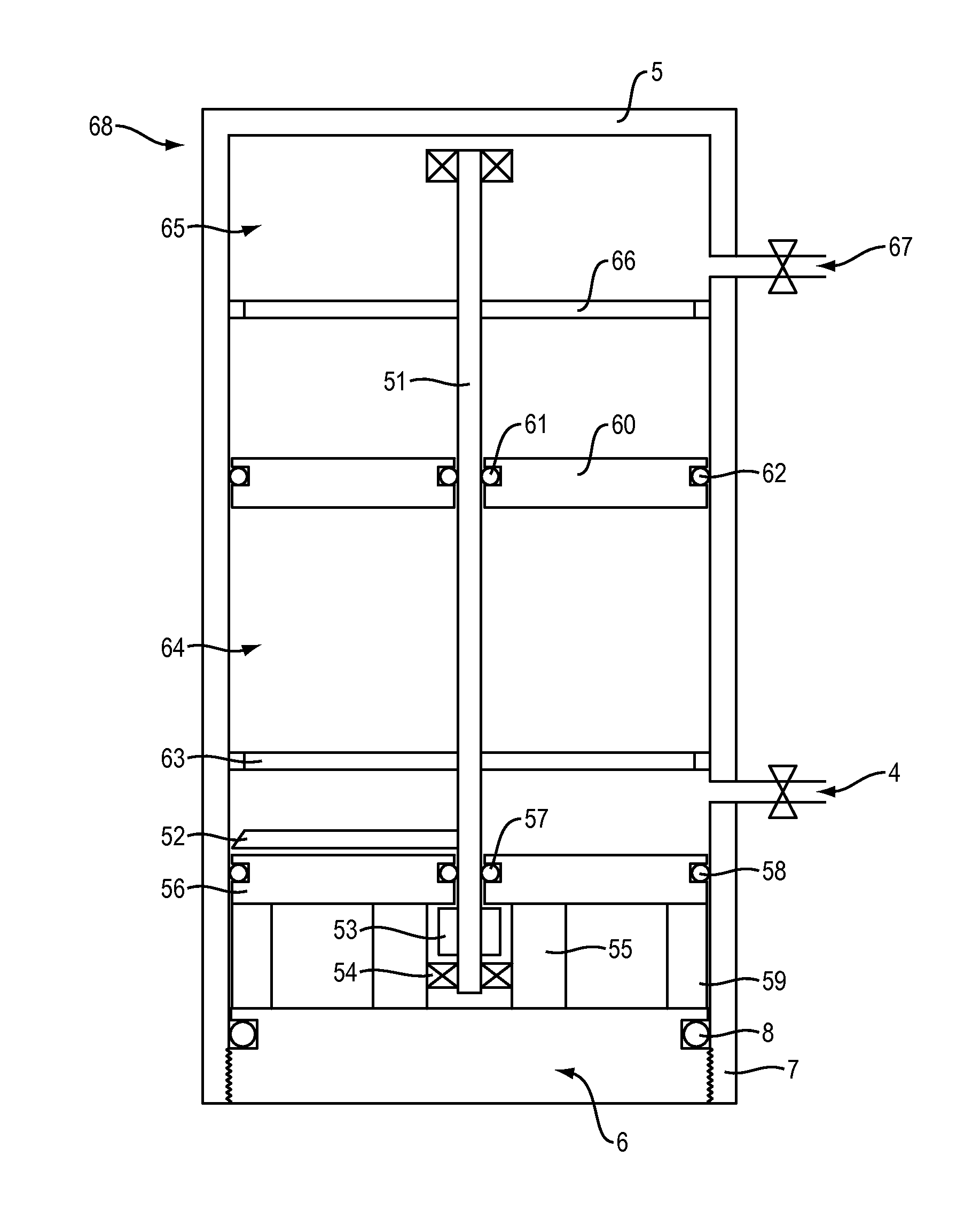
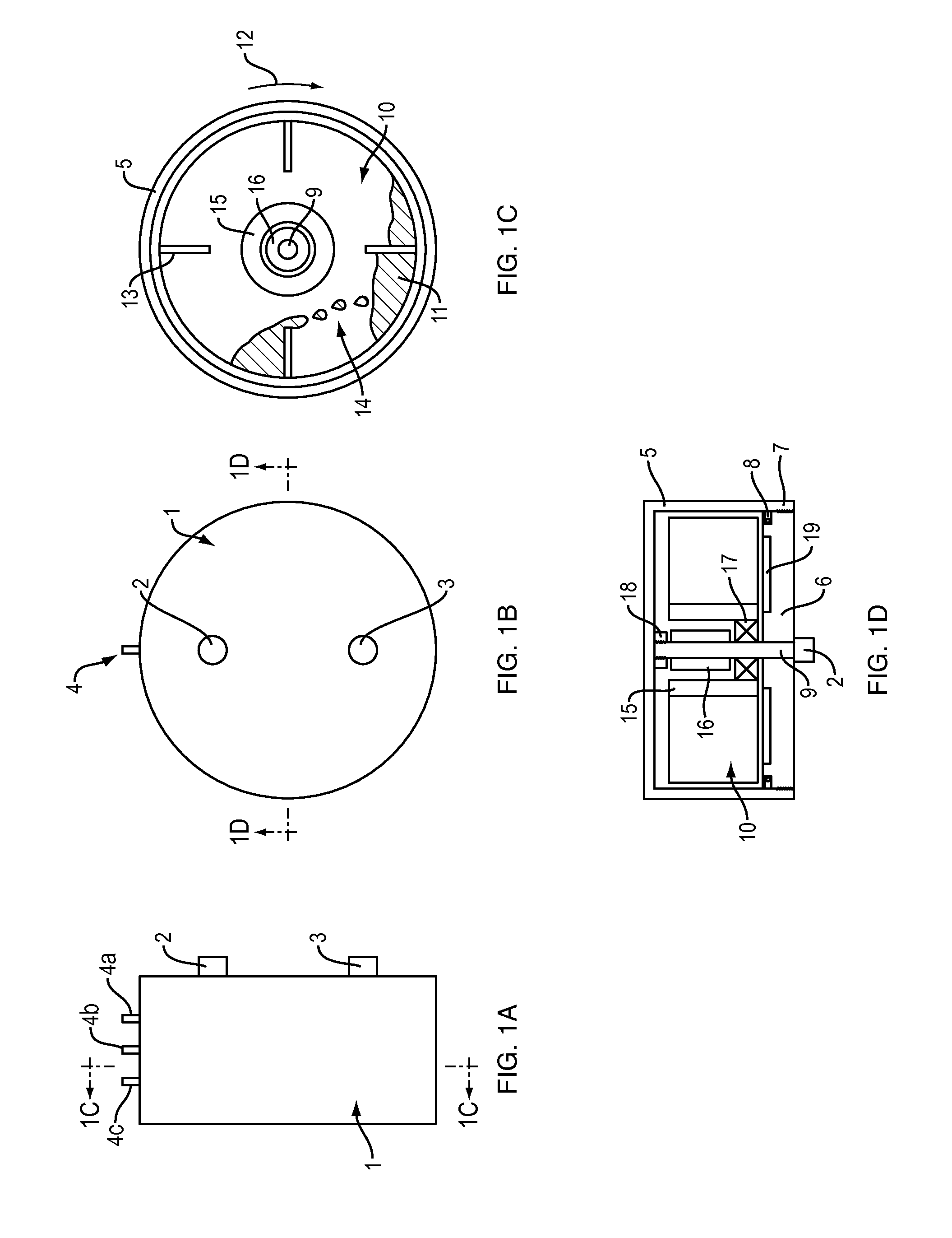
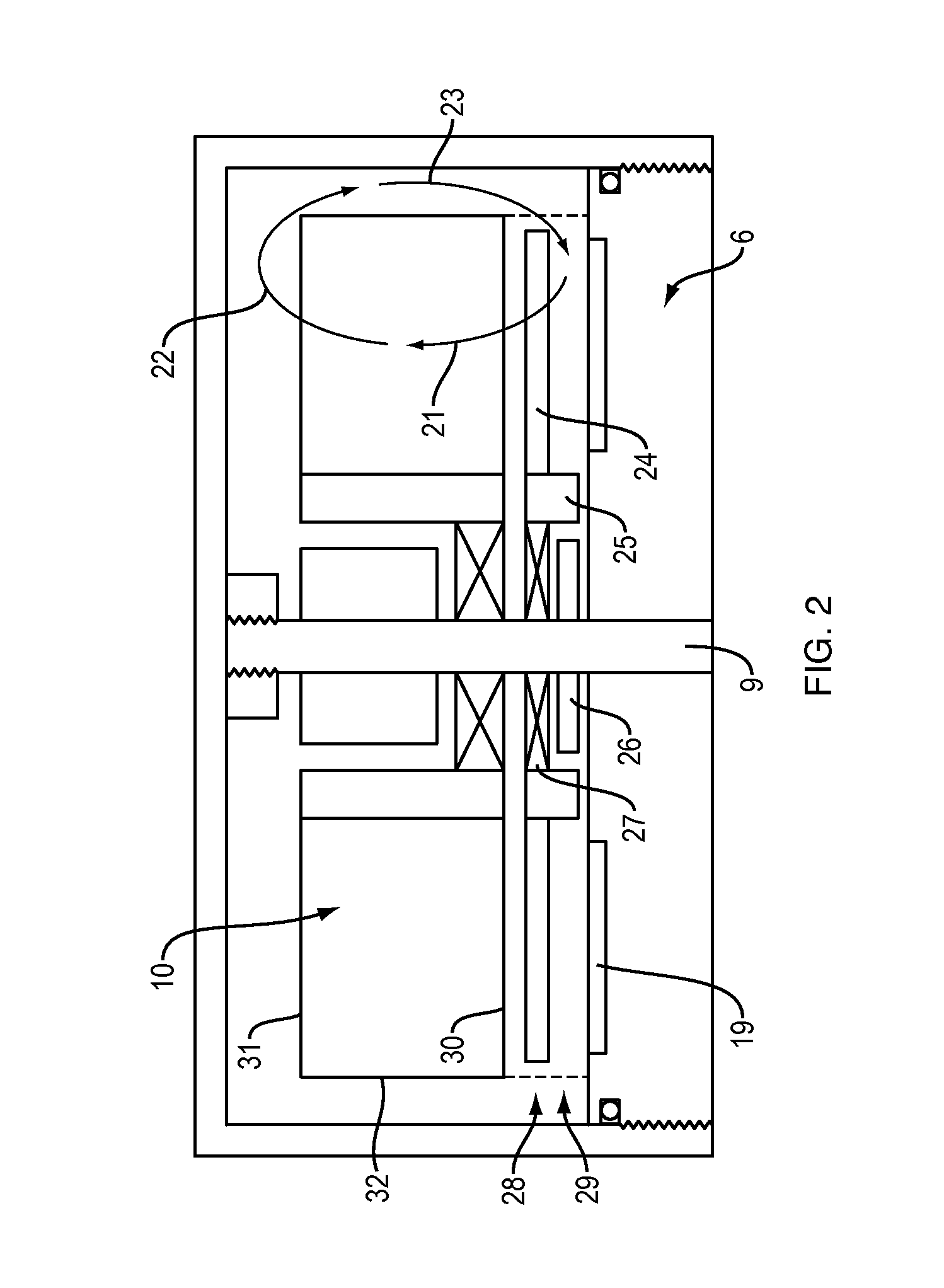
[0040]In one example embodiment, cartridges in accordance with various embodiments of the present invention may be utilized in the processing of solid biomass and the extraction of volatile components from the biomass in a supercritical fluid environment. There are a number of potential configurations for cartridges in accordance with the principles of the present invention. FIGS. 1A-1D and 2 illustrate an exemplary drum rotor cartridge, and FIG. 4 illustrates an exemplary mixing cartridge, but it should be understood that any number of cartridge configurations may be practicable.

[0041]FIGS. 1A through 1D provide respectively, a side view, an end view and two cross-sectional views of an embodiment of the present invention. FIG. 1A provides a side view of a drum rotor cartridge in accordance with an embodiment of the present invention. The side view of FIG. 1A shows a drum rotor cartridge 1, with various ports that may be useful during feedstock processing....


PUM

PropertyMeasurementUnit
pressureaaaaaaaaaa
pressureaaaaaaaaaa
pressureaaaaaaaaaa

Abstract

The system and method described herein provide for the higher production rate fractionation of biomass for the purpose of selectively separating specific volatile components, which may subsequently be used in the production of a renewable liquid fuel, such as gasoline. Increased production rates of processing of biomass or other feedstock is achieved through the use of sealed reaction chambers, which may be transferred in a sealed configuration between stations in a multi-station processing system. Also, the present invention considers the use of piston assemblies for the dual functions of controlling fluid intake and exhaust (in combination with valves) and for providing a more robust and more cost effective sealing mechanism. The present invention may also achieve improved uniformity of biomass processing through the introduction of a mechanical agitator designed to mix the biomass during processing.

Description

RELATED APPLICATIONS[0001]This application is a continuation of U.S. patent application Ser. No. 13 / 687,449, filed Nov. 28, 2012, and claims the benefit of the following U.S. Provisional Patents Applications: Ser. No. 61 / 564,194, titled “System and Method for Producing Renewable Fuel Using Sealed Cartridges” filed Nov. 28, 2011; Ser. No. 61 / 564,195, titled “System and Method for Producing Renewable Fuel Using Stationary Pressure Chambers” filed Nov. 28, 2011; Ser. No. 61 / 569,058, titled “System and Method for Producing Renewable Fuel Using Sealed Cartridges” filed Dec. 9, 2011; and Ser. No. 61 / 569,053, titled “System and Method for Producing Renewable Fuel Using Stationary Pressure Chambers” filed Dec. 9, 2011. All of these applications are hereby incorporated by reference herein.BACKGROUND[0002]1. Field of Invention[0003]The invention relates to a system and method of using stationary pressure chambers and sealed cartridges to produce renewable fuel from biomass.[0004]2. Discussion...

Claims


Application Information

Patent Timeline
Patent Type & Authority Applications(United States)
IPC IPC(8): C10B27/06C10B53/02C10B37/00
CPCC10B27/06C10B53/02C10B37/00C10G3/42C10G2300/1011Y02P30/20Y02E50/10B01J19/18B01J7/00
Inventor STRIMLING, JON
Owner STRIMLING JON
Learn More