
Apparatus and method for discharging battery

a battery and apparatus technology, applied in battery/fuel cell control arrangement, hybrid vehicles, electric devices, etc., can solve problems such as environmental pollution, electric vehicles are not commercially used, and voltage deviation between battery cells caused by structural differences is inevitabl

Active Publication Date: 2016-06-09
HYUNDAI MOBIS CO LTD
View PDF5 Cites 8 Cited by
  • Summary
  • Abstract
  • Description
  • Claims
  • Application Information

AI Technical Summary

Benefits of technology

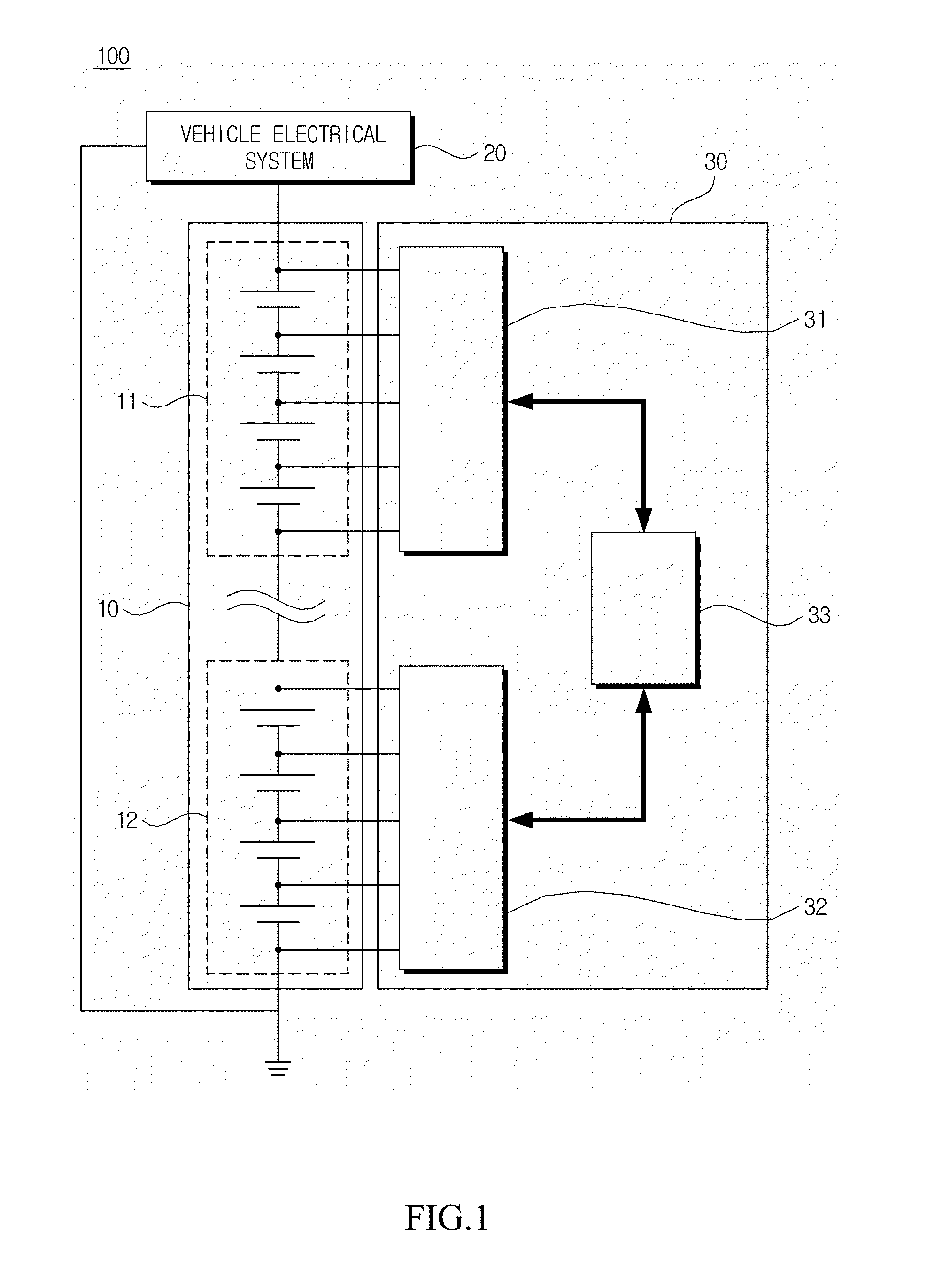
The present invention is about a device and method for discharging batteries. The invention prevents the battery cell balancing circuit from getting overheated while discharging the battery. This can help prevent fire or explosions caused by high voltage batteries.

Problems solved by technology

A vehicle which uses an internal combustion engine using fossil fuel such as gasoline or heavy oil as a major fuel seriously causes environmental contamination such as air pollution.
However, the electric vehicle is not commercially used due to problems such as a heavy weight of a battery, a limitation of a battery capacity, and a time to charge the battery.
As described above, a voltage deviation between battery cells caused by a structural difference is inevitably generated in the battery management system to which the plurality of battery cells is coupled.
The voltage deviation hinders uniformity of the voltage of the battery and in turn deteriorates the battery so that a lifespan of the battery is shortened.
In the meantime, when collision of the vehicle which uses a high voltage battery or vehicle damage occurs, a leakage current may be generated from the high voltage battery to a chassis of the vehicle.
The leakage current of the battery may cause a negligent accident such as fire in the vehicle or electric shock to a driver.
However, according to the related art, all cells are simultaneously balanced, so that excessive heat which is 100° C. or higher is generated in the balancing circuit and risk of fire or explosion may be raised as problems.

Method used


Image

  • Apparatus and method for discharging battery
  • Apparatus and method for discharging battery
  • Apparatus and method for discharging battery

Examples


Embodiment Construction

[0034]Hereinafter, exemplary embodiments of the present invention will be described in detail with reference to the accompanying drawings.

[0035]When the exemplary embodiment is described, a technology which is well known in the technical field of the present invention and is not directly related with the present invention will not be described. The reason is that unnecessary description is omitted to clearly transmit the gist of the present invention without obscuring the gist.

[0036]By the same reason, in the accompanying drawings, some parts are exaggerated, omitted, or schematically illustrated. Further, an actual size is not fully reflected to the size of each component. In the drawings, like reference numerals denote like components.

[0037]Hereinafter, a battery discharging apparatus and a method thereof of a battery management system according to an exemplary embodiment of the present invention will be described with reference to the accompanying drawings.

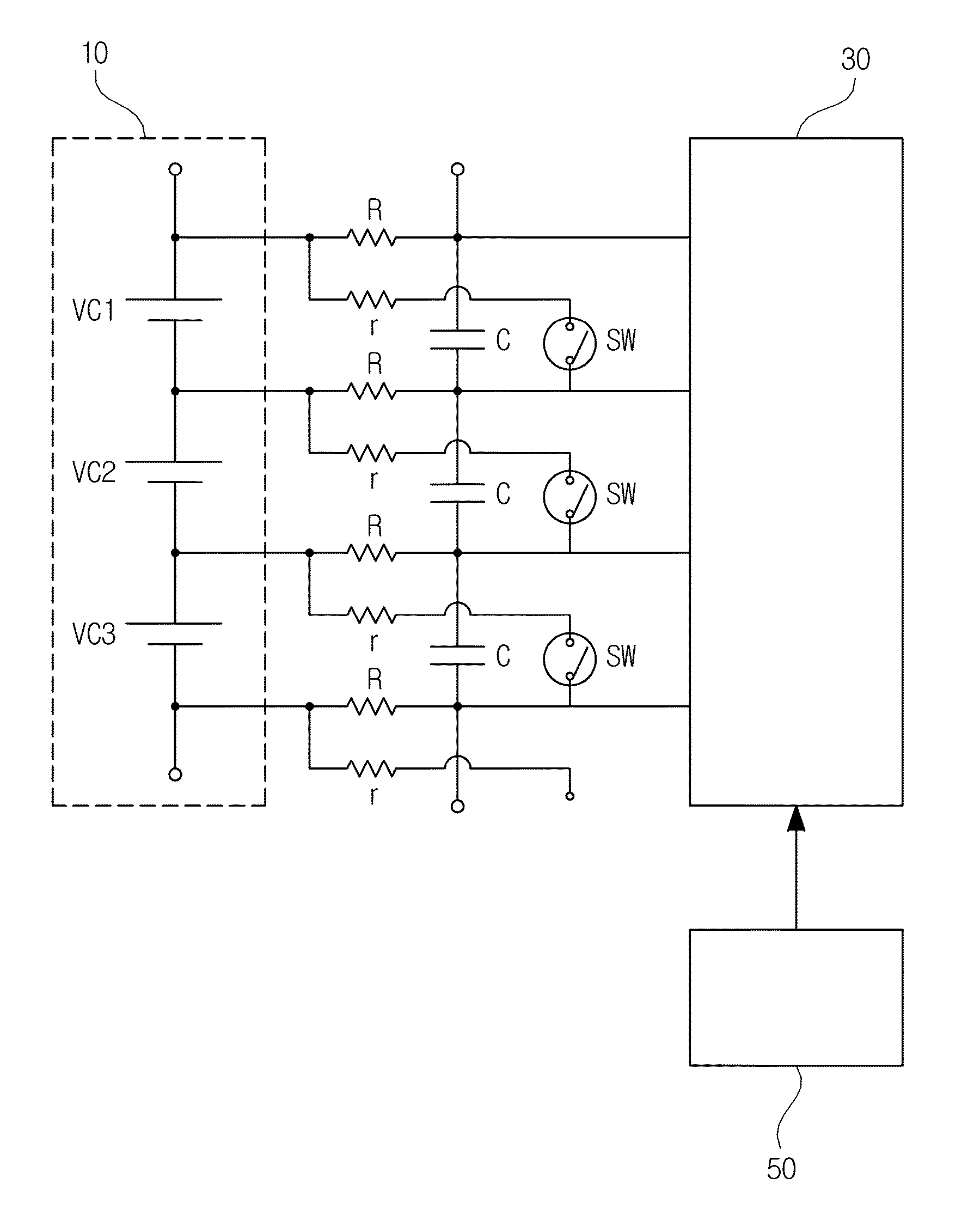
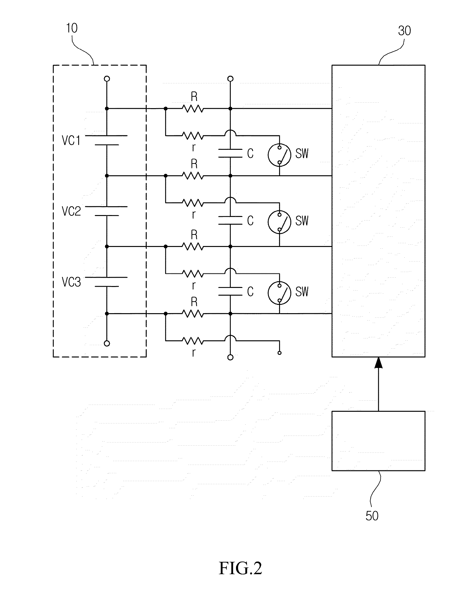
[0038]FIG. 2 is a block...


PUM


Abstract

The present invention relates to a battery discharging apparatus and a method thereof of a battery management system and an exemplary embodiment of the present invention provides a battery discharging apparatus, including: a battery module including a plurality of battery cells; a discharging element which is connected to the battery cells through switches to discharge a voltage of the battery cells; a detecting unit which detects an abnormal state of a vehicle; and a control unit which is connected to the battery module to monitor a charged / discharged status of the battery cells of the battery module and controls the switches to balance the battery cells, in which when the control unit receives a vehicle abnormal state signal from the detecting unit, the control unit controls the switches to be turned on / off at a predetermined duty ratio to discharge the battery cell.

Description

CROSS-REFERENCE TO RELATED APPLICATIONS[0001]This application claims priority to and the benefit of Korean Patent Application No. 10-2014-0175280 filed in the Korean Intellectual Property Office on Dec. 8, 2014, the entire contents of which are incorporated herein by reference.TECHNICAL FIELD[0002]This specification relates to a battery management system which is used for an apparatus using electric energy, and more particularly, to a battery discharging apparatus and a method thereof in a high voltage battery management system used in a hybrid vehicle and an electric vehicle.BACKGROUND ART[0003]Recently, various apparatuses which use high voltage batteries, such as industrial equipment, home appliances, and vehicles have become more common. Specifically, the high voltage batteries are more actively used in a vehicle technology field.[0004]A vehicle which uses an internal combustion engine using fossil fuel such as gasoline or heavy oil as a major fuel seriously causes environmental...

Claims


Application Information

Patent Timeline
IPC IPC(8): B60L11/18
CPCB60L11/1861B60L11/1866B60L58/21H01M10/4207H01M10/441H01M2010/4271B60L3/0046B60L2240/80B60L58/12B60L58/16B60L58/22B60L58/24Y02E60/10Y02T10/70B60W10/26B60W20/00Y02T10/92
Inventor PARK, JAE-SEONG
Owner HYUNDAI MOBIS CO LTD
Learn More