
Waterproof Socket

a wall socket and water-proof technology, applied in the direction of coupling devices, coupling devices, coupling bases/cases, etc., can solve the problems of easy short-circuit, high risk of water or moisture accumulation, and serious accidents, and achieve the effect of maximizing the safety of the wall sock

Active Publication Date: 2016-06-02
YANG JIAMING +1
View PDF10 Cites 11 Cited by
  • Summary
  • Abstract
  • Description
  • Claims
  • Application Information

AI Technical Summary

Benefits of technology

The invention is a waterproof socket that prevents water or moisture from getting inside the electrical components. It can be installed on walls, floors, or extension cords. When the plug is not connected, the upper and lower seals are sealed, and when the plug is connected, the plug works with layers of sealing material to prevent water from getting inside. The screw cover can also keep water from getting inside the bottom of the socket. The waterproof effect is simple and efficient, and the socket can be used with different types of wires.

Problems solved by technology

When there is water entering into the socket, short circuit occurs easily.
It will cause serious accidents especially in some areas having a higher chance of water or moisture built up, such as a bathroom, a kitchen or the like.
For this open / close structure, when the waterproof cover is forgotten to cover the socket, it does not have a waterproof effect, and also it does not have the waterproof effect when the plug is connected with the socket.
However, it cannot prevent the water from entering from a side or bottom of the socket.
In other words, the socket does not have the waterproof effect to prevent water or moisture entering into the socket at any side.

Method used


Image

  • Waterproof Socket
  • Waterproof Socket
  • Waterproof Socket

Examples


Embodiment Construction

[0037]The following description is disclosed to enable any person skilled in the art to make and use the present invention. Preferred embodiments are provided in the following description only as examples and modifications will be apparent to those skilled in the art. The general principles defined in the following description would be applied to other embodiments, alternatives, modifications, equivalents, and applications without departing from the spirit and scope of the present invention.

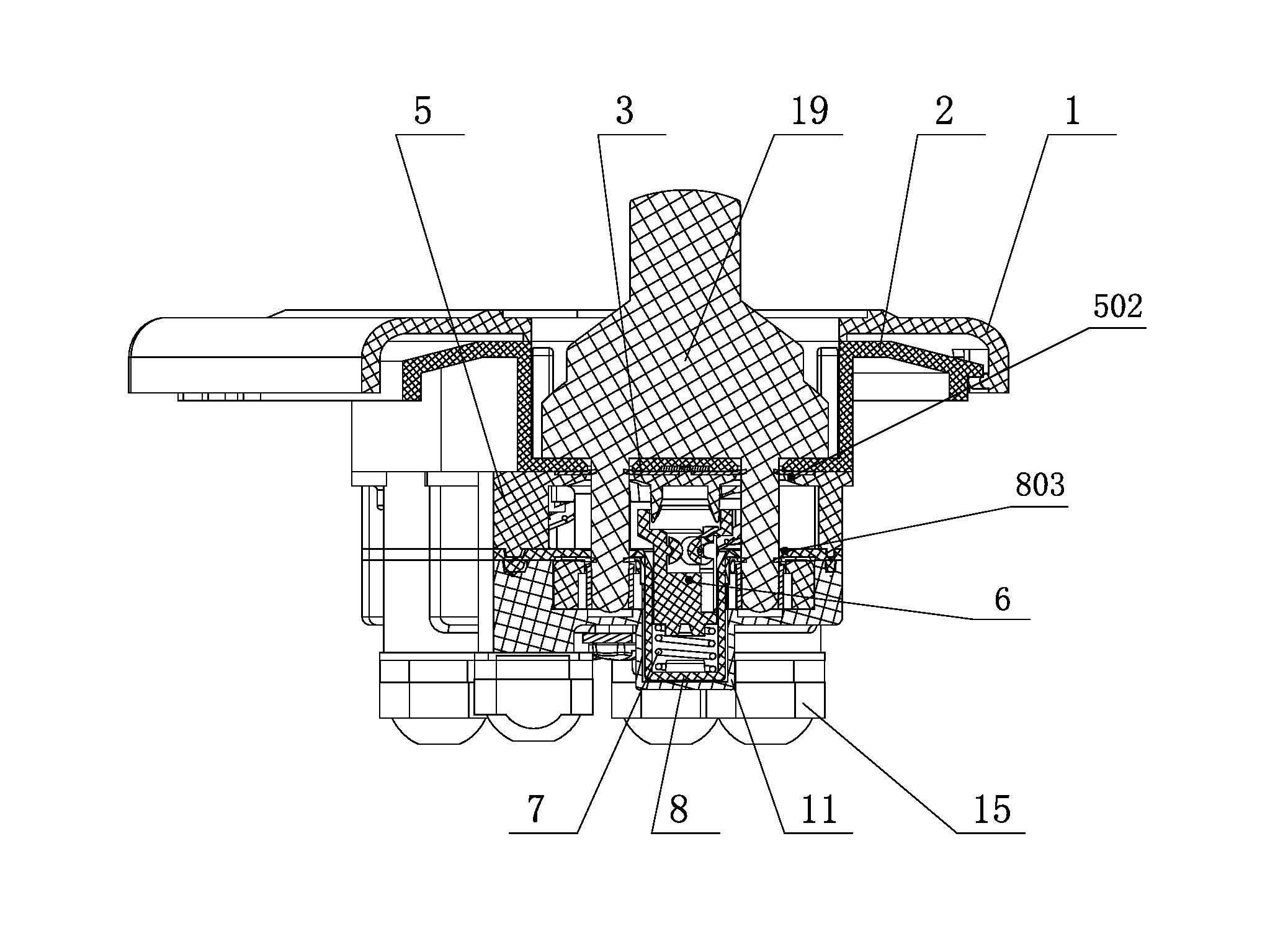
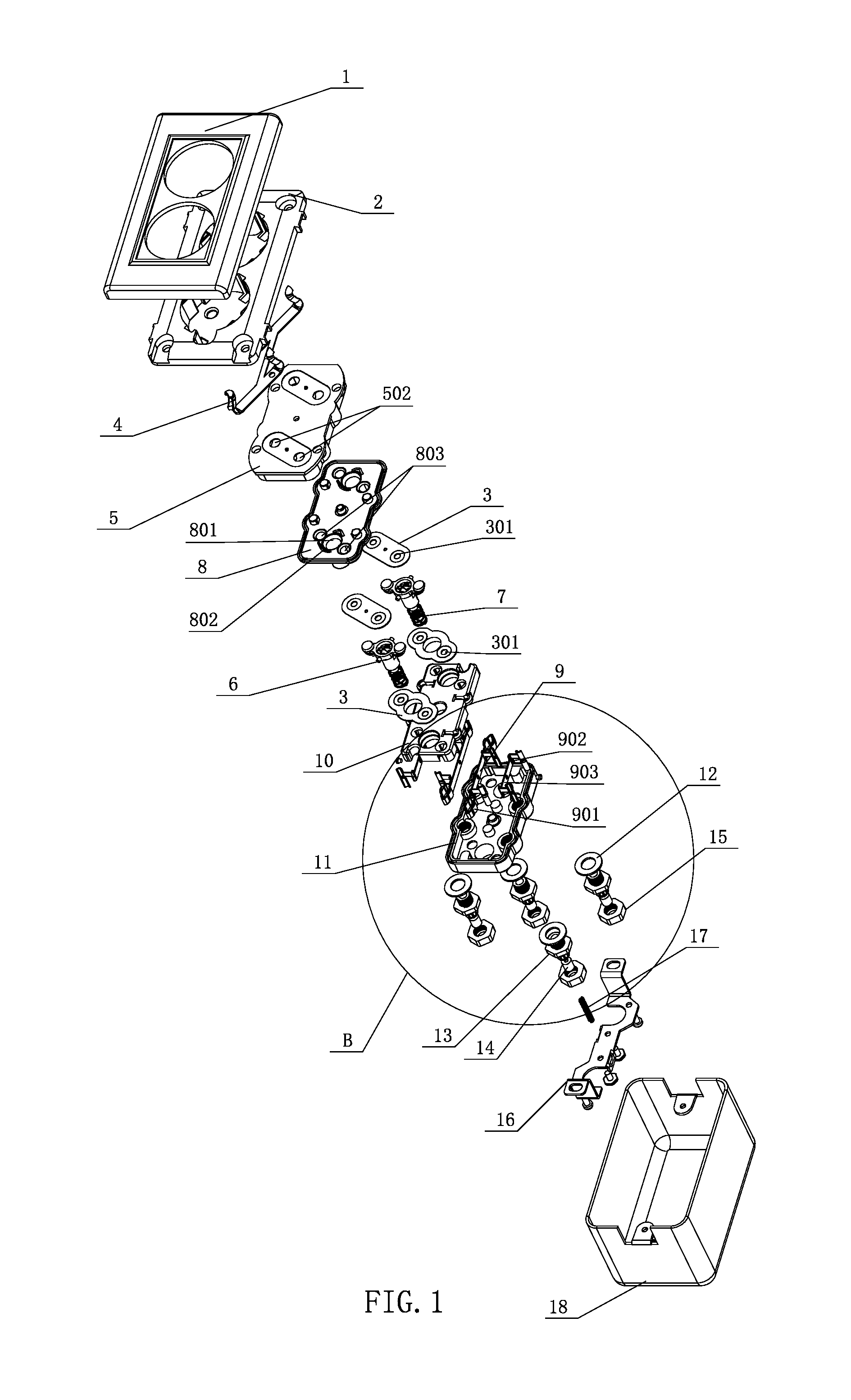
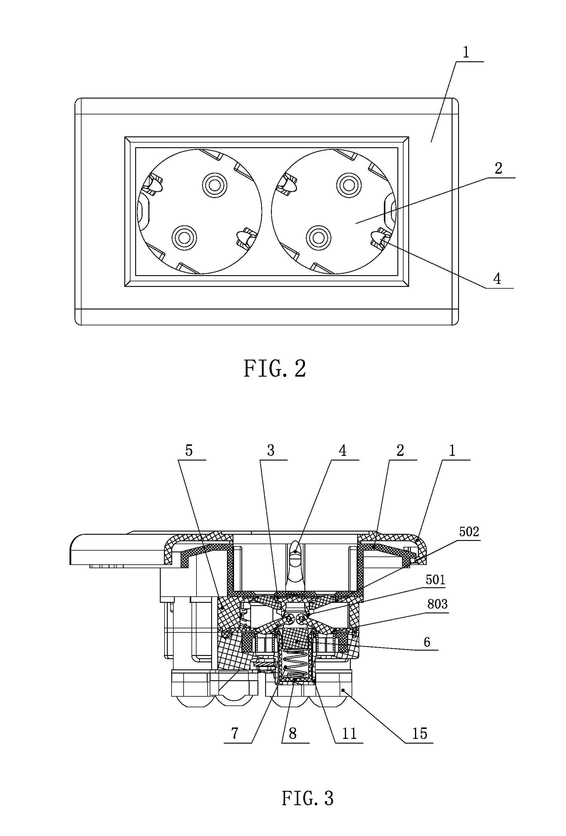
[0038]As shown in FIGS. 1 to 4, a waterproof socket according to a preferred embodiment of the present invention is illustrated, wherein the waterproof socket comprises a socket panel 2, an outer casing 18 coupled to the socket panel 2, a retention frame 5 and a socket base 11, wherein the retention frame 5 and the socket base 11 are provided between the socket panel 2 and the outer casing 18. The waterproof socket further comprises a face cover 1 coupled in front of the socket panel 2 for enhanc...


PUM


Abstract

A waterproof socket includes an inner core fixing base disposed between a retention frame and a socket base. Lower insertion holes are coaxial with an output terminal and are formed in the inner core fixing base. An accommodating groove is formed between two lower insertion holes. A waterproof inner core is disposed in the accommodating groove. The waterproof inner core includes a main body movably inserted in the accommodating groove. Two upper seal doors are sealed at upper insertion holes of the retention frame and are disposed on two upper sides of the main body, and two swing rods are symmetrically disposed below the upper seal doors. One end of each of the swing rod is hinged to the main body, and the other end of the swing rod is provided with a lower seal door for sealing the lower insertion holes of the inner core fixing base.

Description

CROSS REFERENCE OF RELATED APPLICATION[0001]This is a non-provisional application that claims priority to international application number PCT / CN2013 / 090458, international filing date Dec. 25, 2013, the entire contents of each of which are expressly incorporated herein by reference.NOTICE OF COPYRIGHT[0002]A portion of the disclosure of this patent document contains material which is subject to copyright protection. The copyright owner has no objection to any reproduction by anyone of the patent disclosure, as it appears in the United States Patent and Trademark Office patent files or records, but otherwise reserves all copyright rights whatsoever.BACKGROUND OF THE PRESENT INVENTION[0003]1. Field of Invention[0004]The present invention relates to an electrical wall socket, and in particular to a waterproof socket to prevent water or moisture entering into the electrical components of the waterproof socket for maximizing the safety of the wall socket.[0005]2. Description of Related A...

Claims


Application Information

Patent Timeline
Patent Type & Authority Applications(United States)
IPC IPC(8): H01R13/52H01R25/00
CPCH01R13/5202H01R13/521H01R25/006H01R13/52H01R13/5205H01R13/5219H01R24/78H01R13/4532H01R13/4538H01R13/5213H01R13/453
Inventor YANG, JIAMING
Owner YANG JIAMING
Learn More