Anisotropic conductive film and manufacturing method therefor
a technology of anisotropic conductive film and manufacturing method, which is applied in the direction of conductive layers on insulating supports, paper/cardboard containers, applications, etc., can solve the problems of interconnected conductive particles between electrodes, conductive failure caused, short circuits, etc., and achieve excellent connection reliability, short circuits, and less short circuits
Inactive Publication Date: 2016-06-02
DEXERIALS CORP
View PDF2 Cites 21 Cited by
- Summary
- Abstract
- Description
- Claims
- Application Information
AI Technical Summary
Benefits of technology
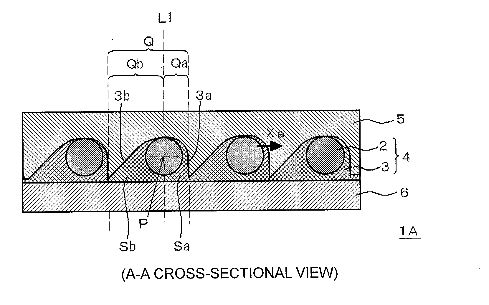
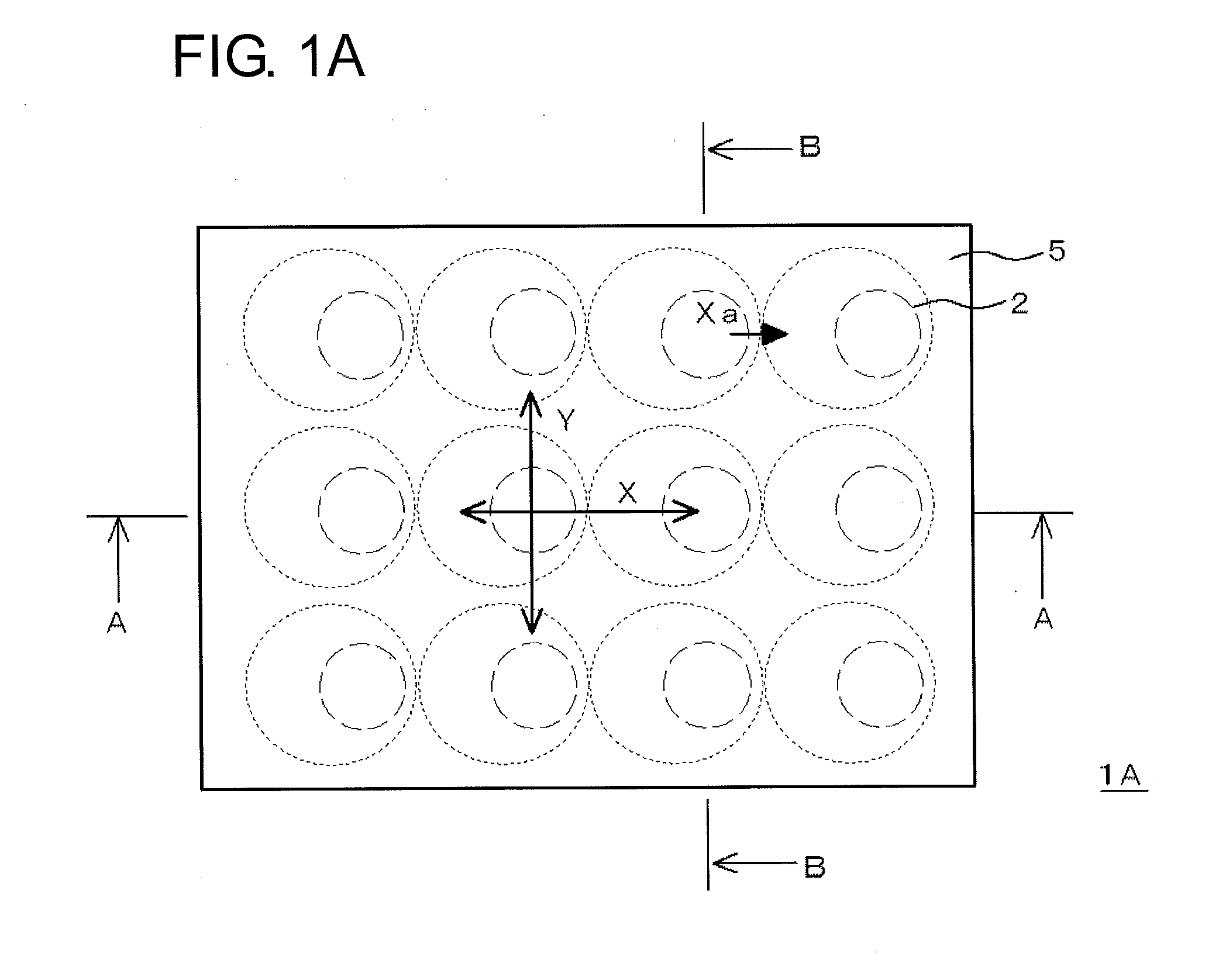
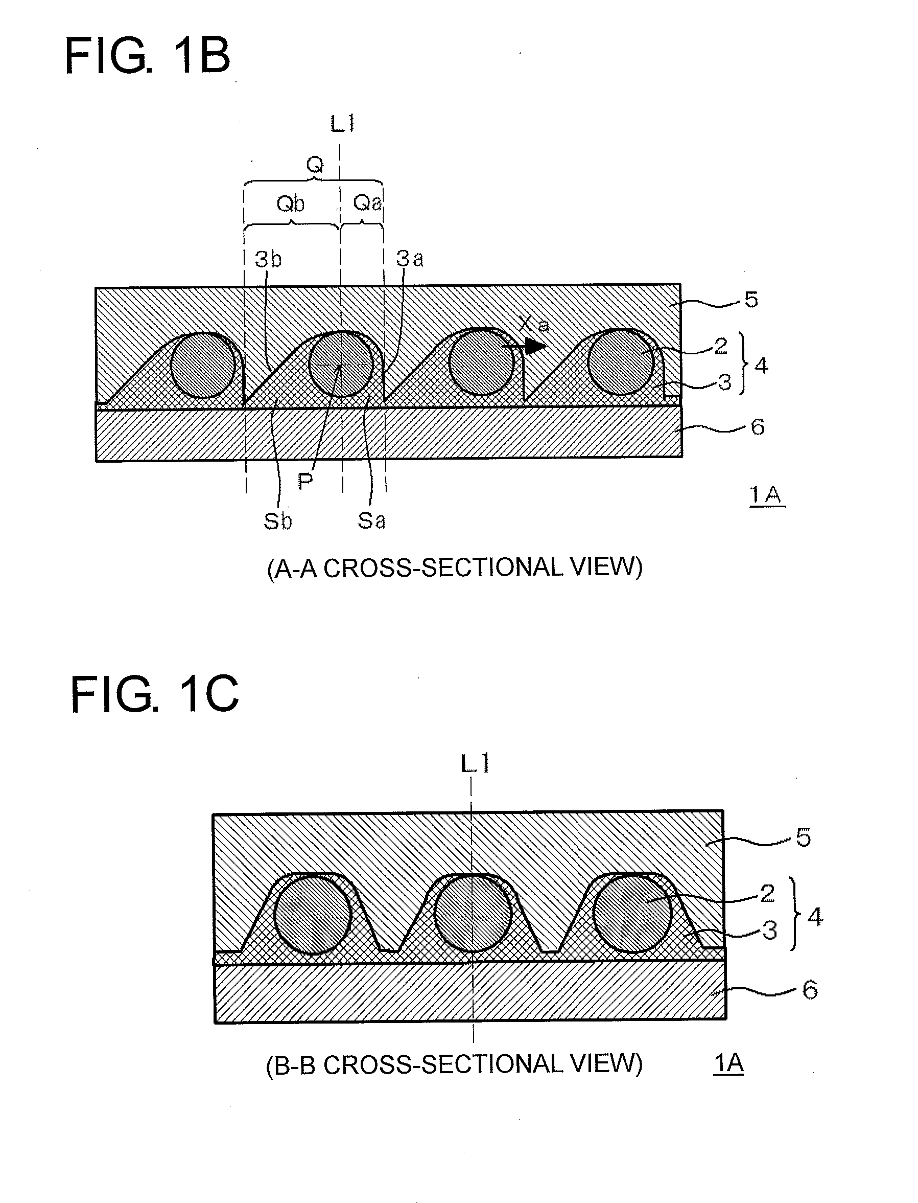
[0016]According to an anisotropic conductive film of the present invention, there is a direction in which a thickness distribution, around an individual conductive particle, of an insulating resin layer holding an array of the conductive particles is asymmetric with respect to the conductive particle. Thus, a flow direction of the conductive particles, when an electronic component is mounted using the anisotropic conductive film, depends on a direction in which a resin amount, around the conductive particles, of the insulating resin layer holding an array of the conductive particles is less. Therefore, when an electronic component is mounted using the anisotropic conductive film, the flow directions of the conductive particles are not biased to a specific site. Thus, short circuits caused by interconnected conductive particles between the electrodes and conductive failure caused by the absence of the conductive particles between the electrodes can be reduced. As such, the connection structure of the present invention, prepared by using the anisotropic conductive film, causes less short circuits and conductive failure and is excellent in connection rel
Problems solved by technology
When electrodes having a narrow pitch are connected via an anisotropic conductive film, short circuits caused by interconnected conductive
Method used
View moreImage
Smart ImageViewing Examples
Examples
 PUM
| Property | Measurement | Unit |
|---|---|---|
| Thickness | aaaaa | aaaaa |
| Electrical conductor | aaaaa | aaaaa |
| Area | aaaaa | aaaaa |
Abstract
An anisotropic conductive film includes a conductive particle array layer in which a plurality of conductive particles are arrayed in a prescribed manner and held in an insulating resin layer. The anisotropic conductive film has a direction in which a thickness distribution, around the individual conductive particle, of the insulating resin layer holding the array of the conductive particles is asymmetric with respect to the conductive particle. The direction in which the thickness distribution is asymmetric is aligned in the same direction in the plurality of conductive particles. When an electronic component is mounted using this anisotropic conductive film, short circuits and conductive failure can be reduced.
Description
TECHNICAL FIELD[0001]The present invention relates to an anisotropic conductive film and a method of producing the same.BACKGROUND ART[0002]An anisotropic conductive film is formed by dispersing conductive particles in an insulating adhesive and widely used for mounting an electronic component, such as an IC chip. Recent advances in the miniaturization of electronic apparatuses have also led to the miniaturization of mounting components. The shift to using narrow pitches is progressing and electrode pitches are, for example, narrowed to several tens of μm. When electrodes having a narrow pitch are connected via an anisotropic conductive film, short circuits caused by interconnected conductive particles between the electrodes and conductive failure caused by the absence of conductive particles between the electrodes tends to occur.[0003]To solve such problems, arranging conductive particles regularly on an anisotropic conductive film has been considered. For example, a method of arra...
Claims
Login to View More Application Information
Patent Timeline
 IPC IPC(8): H01L23/00
CPCH01L24/29H01L2224/293H01L2224/2929H01R4/04H05K3/323H01L2224/271H01L2224/29357H01L2224/2939H01L2224/27005H01L24/27H01L2224/29018H01L2224/29076H01L2224/29082H01L2224/2919H01L2224/29339H01L2224/29344H01L2224/29347H01L2224/29355H01L2224/29364H01L2224/29499H01L2224/294H01L2224/2711H01L2924/00014H01B1/20H01B5/14H01B5/16H01R11/01B32B2457/00B32B3/06B32B2305/07B32B3/30B32B2260/046B32B5/145B32B3/263B32B2307/706H01L2224/29083
Inventor SARUYAMA, KENICHIAKUTSU, YASUSHI
Owner DEXERIALS CORP
Features
- R&D
- Intellectual Property
- Life Sciences
- Materials
- Tech Scout
- Unparalleled Data Quality
- Higher Quality Content
- 60% Fewer Hallucinations
Learn More Browse by: Latest US Patents, China's latest patents, Technical Efficacy Thesaurus, Application Domain, Technology Topic, Popular Technical Reports.
© 2025 PatSnap. All rights reserved.Legal|Privacy policy|Modern Slavery Act Transparency Statement|Sitemap|About US| Contact US: help@patsnap.com


