Display device

Inactive Publication Date: 2016-06-02
JAPAN DISPLAY INC
View PDF6 Cites 2 Cited by
  • Summary
  • Abstract
  • Description
  • Claims
  • Application Information

AI Technical Summary

Benefits of technology

The present invention aims to provide a display device that can prevent or suppress bending of the display panel when a cover member is not provided, which can lead to a spot occurring on the displayed image. This is achieved by supporting the display panel in a way that prevents damage to its rear surface and avoids bending of the display panel during touch input.

Problems solved by technology

In addition, a spot occurs on an image displayed on the display device due to bending of the display panel.

Method used


Image

  • Display device
  • Display device
  • Display device

Examples


embodiment

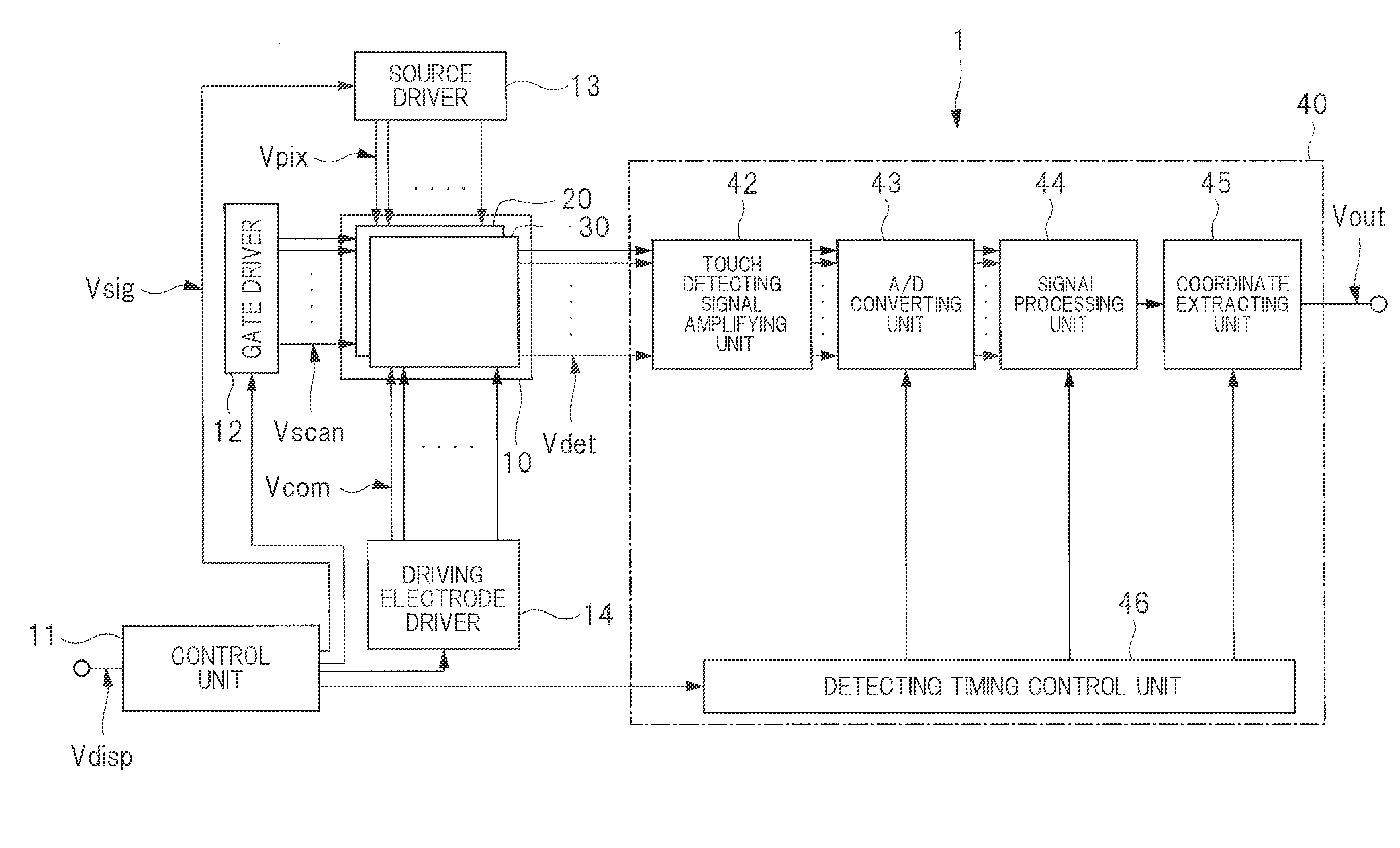
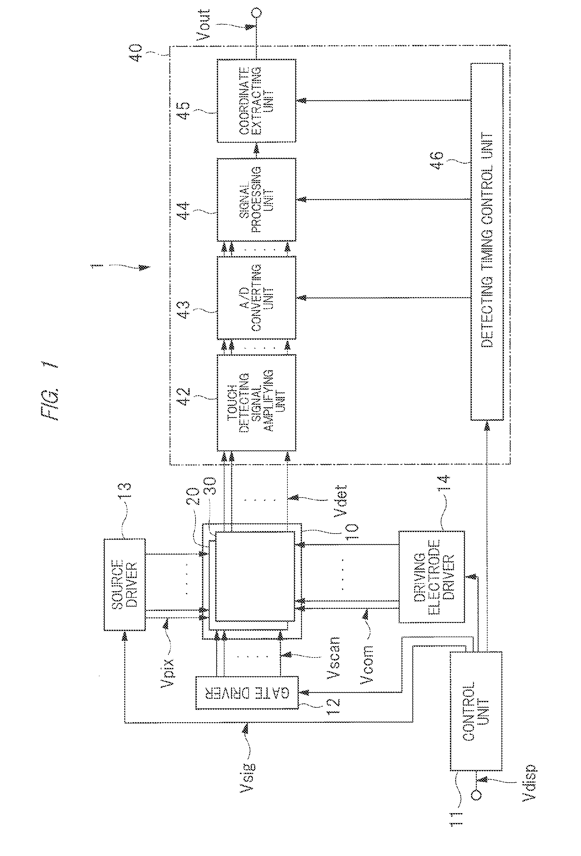
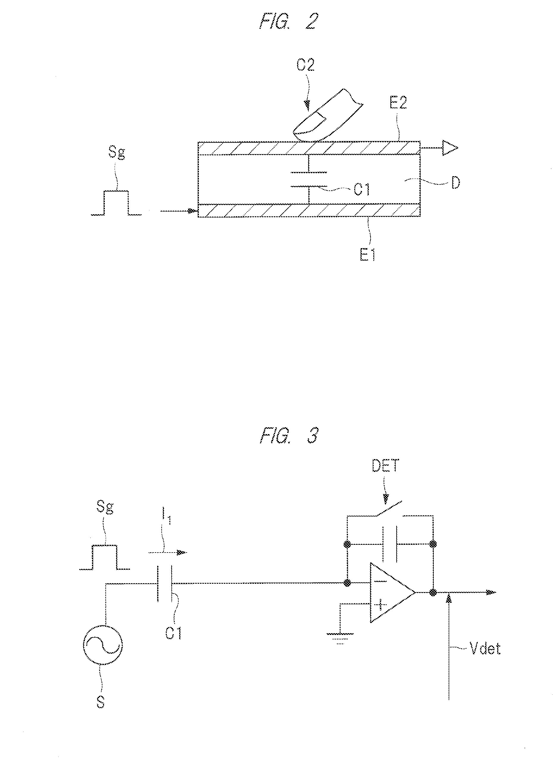
[0036]First, an example in which a display device provided with a touch panel as an input device is applied to an in-cell type liquid crystal display device with a touch detection function will be described as the embodiment. Also, in this specification, an input device refers to an input device that detects an electrostatic capacitance varying depending on a capacitance of an object approaching or contacting at least an electrode. In this case, a method of detecting an electrostatic capacitance includes not only mutual capacitance method of detecting an electrostatic capacitance between two electrodes but also a self-capacitance method of detecting an electrostatic capacitance of one electrode. Also, a liquid crystal display device with a touch detection function refers to a liquid crystal display device in which a detecting electrode for touch detection is provided in any one of a first substrate and a second substrate which are included in a display panel. In addition, in the emb...


PUM


Abstract

A display device includes a display panel having a top surface and a bottom surface on the opposite side of the top surface and displays an image on the top surface, and a cover member covers the bottom surface of the display panel. The display panel includes a detecting element for detecting an object approaching the top surface. Also, the cover member is adhered to the bottom surface via the adhesive layer.

Description

CROSS-REFERENCE TO RELATED APPLICATIONS[0001]The present application claims priority from Japanese Patent Application No. 2014-240376 filed on Nov. 27, 2014, the content of which is hereby incorporated by reference into this application.TECHNICAL FIELD OF THE INVENTION[0002]The present invention relates to a display device, and particularly relates to a display device having an electrostatic capacitive type input device.BACKGROUND OF THE INVENTION[0003]In recent years, technique of attaching an input device referred to as a touch panel or a touch sensor to a display plane side of a display device and detecting and outputting an input position when input operations are performed by contacting the touch panel with a finger or an input tool such as a stylus pen has been known. Such display devices having a touch panel are widely used in portable information terminals such as mobile phones in addition to computers.[0004]One detecting method for detecting contact positions at which a fin...

Claims


Application Information

Patent Timeline
IPC IPC(8): G06F3/044G02F1/1333G02F1/1335G06F3/041
CPCG06F3/044G06F3/0412G06F2203/04108G02F1/13338G02F1/133528G06F3/0416G02F2202/28G06F3/04166G06F3/0445G06F3/0446G02F1/133302
Inventor NOGUCHI, KOJIFURUTANI, NAOSUKEISHIGE, OSAMUNAKAMURA, ATSUSHI
Owner JAPAN DISPLAY INC
Why Eureka
Try Eureka