
Signal for identifying traffic lights for computer vision

Inactive Publication Date: 2016-06-02
VILLAR CLOQUELL JAVIER
View PDF1 Cites 17 Cited by
  • Summary
  • Abstract
  • Description
  • Claims
  • Application Information

AI Technical Summary

Benefits of technology

The patent text presents a new signal that can identify each traffic light and ensure the effectiveness of computer vision recognition devices and systems. In some versions, the signal emits infrared or ultraviolet light that can be easily detected by sensors but is not visible to the human eye. This helps prevent any potential confusion for drivers or pedestrians.

Problems solved by technology

However, when crossings are in various directions or include pedestrian islands, traffic lights with sound signals may confuse blind people, posing a hazard of impact or crushing.
These traffics lights pose the same problem already discussed for traffic lights with sound signals.
These lights do not offer a solution for blind people to cross the road.
These computer vision systems are unable to recognize blind or visually impaired people to help them cross the road safely.
These systems to guide blind people have very high installation and maintenance costs.
One of the main reasons why public authorities do not adapt or install traffic lights to ensure that blind or visually impaired people can cross the road safely is their cost of acquisition, installation and maintenance.
Installing traffic lights for blind or visually impaired pedestrians that are only used occasionally implies a cost that the governments concerned are rarely willing or able to bear.
In some locations, such adapted traffic lights are thus limited exclusively to the city center or to crosses with much pedestrian traffic.
Devices using computer vision software to detect traffic lights and identify their state face certain limitations.
Some of the challenges to the recognition of traffic lights with computer vision software are:To ensure that the software correctly recognizes the traffic light, the camera has to face the relevant traffic light straight ahead or with a very small variation angle.
If the camera faces it from one side, it will interpret it as a traffic light facing elsewhere and will not identify it as the one to be used to cross the road.At crossings where traffic lights are at a distance greater than 20 meters, there is no guarantee that the software detects that there is a traffic light.
If the traffic light is not recognized as such by the software, its state cannot be identified.Crossings where there is more than one traffic light facing frontally confuse the computer vision software, since it may recognize a traffic light that is not the one pedestrians want to use.At crossings with pedestrian islands, the software may wrongly interpret the state of the traffic light in cases where both traffic lights are not in the same state.In darkness or limited visibility conditions, the computer vision software cannot recognize the contours of the traffic light and therefore it cannot recognize it as being a traffic light.There is a variety of models of traffic lights.
The computer vision software may face great challenges and perform poorly if it is to recognize multiple models of traffic lights: Their specifications may differ highly in terms of size, shape, lamp colors, number of lights, distribution of lights, presence of a countdown timer, etc.Electronic guidance devices are carried by a pedestrian, who may be stationary or moving.
Capture of motion images creates distortion and fuzziness in the images, which poses a challenge to the recognition of traffic lights by computer vision software.When the camera stops detecting the traffic light, it cannot know if the blind person is following the correct path.Global positioning systems like GPS have a margin of error of between 3 and 10 meters.
However, in the case of electronic guiding devices with computer vision, if the location of the traffic light is determined by GPS, there are no guarantees that the correct traffic light will be identified.
All these problems involved in the recognition of pedestrian traffic lights and their status may cause serious injury or death to blind or visually impaired pedestrians.

Method used


Image

  • Signal for identifying traffic lights for computer vision
  • Signal for identifying traffic lights for computer vision
  • Signal for identifying traffic lights for computer vision

Examples


Embodiment Construction

[0025]The present invention provides solutions to the various problems that arise in the recognition of pedestrian traffic lights by computer vision.

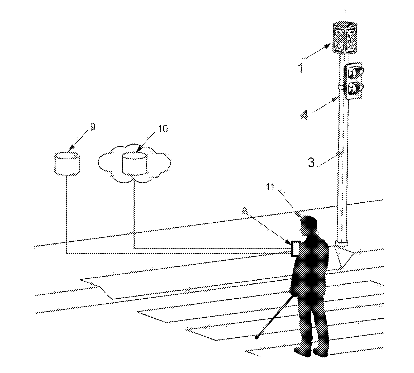
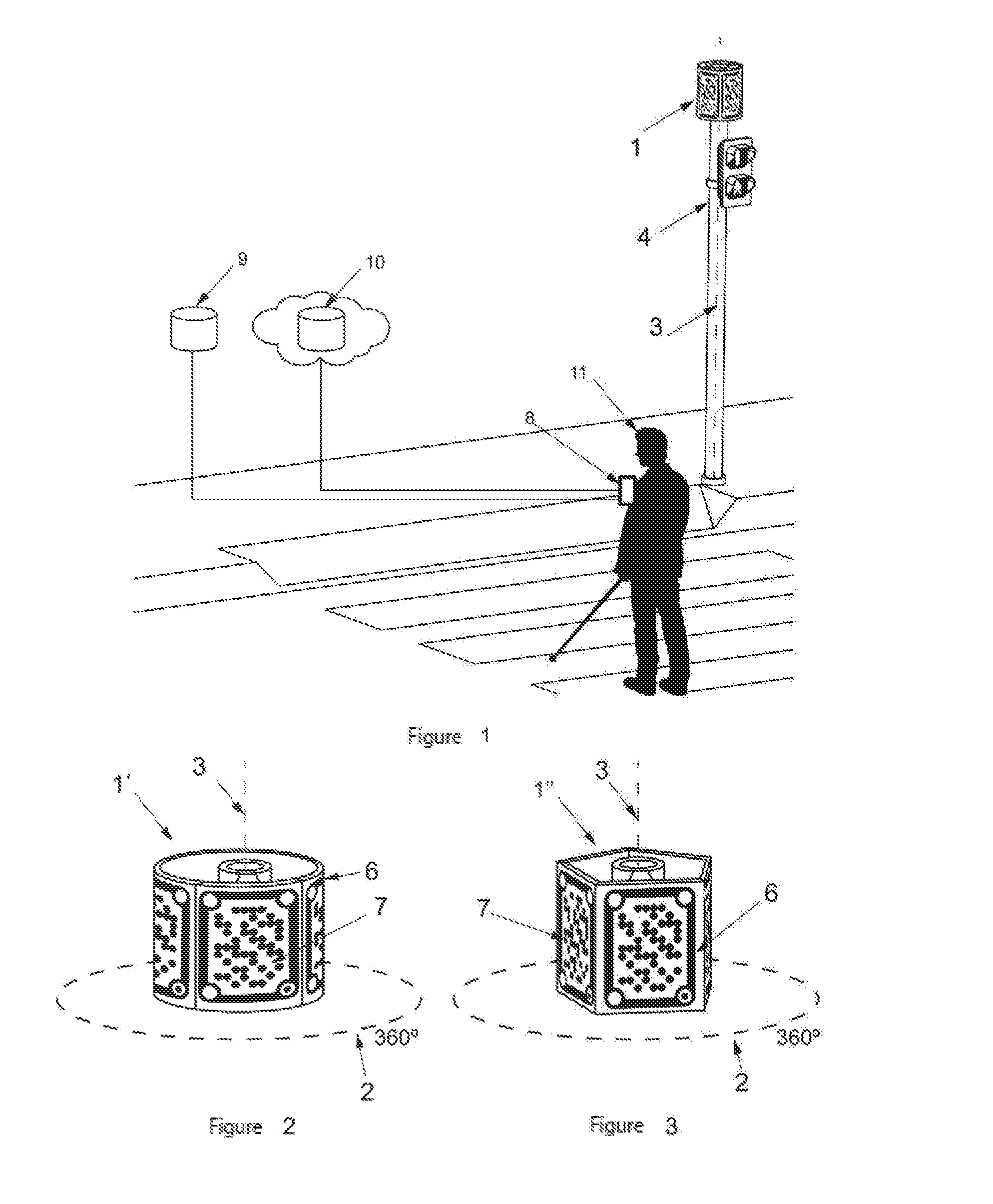
[0026]It presents a new signal containing information that identifies each traffic light and having means to ensure the effectiveness of the devices and systems for computer vision recognition.

[0027]A great advantage of this invention over others is the low cost of adapting the existing traffic lights or including the invention in new traffic lights. These signals need no regular maintenance and their life span equals or exceeds that of the traffic light.

[0028]Pedestrians, including blind or partially sighted people moving in urban environments, use pedestrian traffic lights or crossings to cross the road safely. To get from one point to another in an urban environment, blind or visually impaired people use electronic guidance devices implemented in specific electronic devices, canes, mobile phones or goggles. Such urban guiding devices...


PUM


Abstract

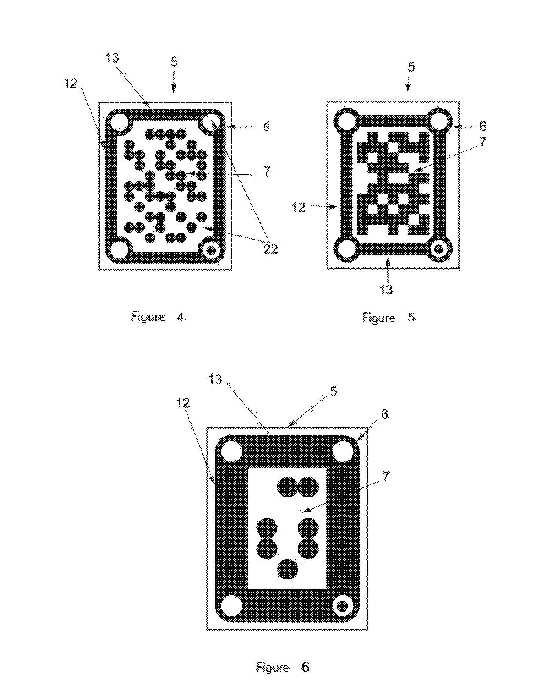
The invention relates to a signal for identifying traffic lights for pedestrians, using an electronic urban guidance device with computer vision, for blind or visually impaired people. The signal is cylindrical or prismatic, has marks that contain encoded information such as the identification of the traffic light, and information characterizing the traffic light and the crossing. The signal can be recognized in 360° and there are versions for a smaller viewing angle. The main signal for identifying the traffic light can have secondary identification signals. In adverse viewing conditions caused by the light or the weather, the signal can be reflective, fluorescent, phosphorescent or can light up in visible, infrared or ultraviolet ranges of the electromagnetic spectrum. Said identification signal can be used to identify other types of urban elements.

Description

TECHNICAL FIELD[0001]The present invention is comprised within the field of urban signs and guidance for blind or visually impaired people interpreted by computer vision.BACKGROUND OF THE INVENTION[0002]In the prior art there are many inventions and products which adapt or improve traffic lights for blind or visually impaired people to cross the road safely at crossings where traffic lights are not adapted.[0003]There are traffic lights that emit sound signals to help blind or visually impaired people cross the road when the pedestrian light is green. These lights work well when crossings are simple. However, when crossings are in various directions or include pedestrian islands, traffic lights with sound signals may confuse blind people, posing a hazard of impact or crushing.[0004]There are traffic lights where blind pedestrians themselves can trigger the audible signals by remote control, electromagnetic signals or other systems depending on the state of the traffic light, as show...

Claims


Application Information

Patent Timeline
Patent Type & Authority Applications(United States)
IPC IPC(8): A61H3/06G09B21/00
CPCG09B21/001A61H3/061G06V20/584A61H3/06G09B21/00G06F18/00
Inventor VILLAR CLOQUELL, JAVIER
Owner VILLAR CLOQUELL JAVIER
Learn More