
Device for dermatological treatment using a laser beam

a laser beam and laser technology, applied in the field of laser beam devices for dermatological treatment, can solve the problems of difficult to predict the temperature reached during treatment using laser devices accurately, the risk cannot be excluded of exceeding 60° c, and the parameters are difficult to measure, so as to eliminate the risk of burning using infrared sensors, the effect of ensuring the effectiveness of treatment and reducing the risk of burns

Inactive Publication Date: 2013-03-14
LABORATOIRE URGO
View PDF10 Cites 16 Cited by
  • Summary
  • Abstract
  • Description
  • Claims
  • Application Information

AI Technical Summary

Benefits of technology

The purpose of this invention is to provide a dermatological treatment device that uses a light beam to effectively treat skin without causing risks of burning through an infrared sensor.

Problems solved by technology

The difficulty with this device lies in the fact that the power of the laser and the length of exposure for each section must be determined in order to heat the edges of the incisions to a temperature that must be precisely between 45° C. and 55° C.
These parameters are difficult to measure during routine use of the device and may be extremely variable depending on the patient and the practitioners' techniques.
As a consequence, it is difficult to predict the temperature reached during treatment using the laser device accurately and the risk cannot be excluded of exceeding 60° C.
The creation of such a device does however present difficulties.
However an additional difficulty then appears, this difficulty residing in the fact that the skin is a medium that gives rise to strong diffusion of light rays.
The result of this is that before being absorbed, photons may follow complex routes within the skin.
However in this case, the power per unit of area of the diffusion of the light beam is from 10 to 15 times greater than the power per unit of area radiated by a body at a temperature of 45° C. The filter, even if it is effective, cannot be sufficient.
Temperature measurements are therefore increasingly false as the power of the light beam increases.
In the light of these additional difficulties linked to the distance away from, or proximity to the zone to be treated, none of the laser devices in the prior art have in practice been combined with an infrared sensor in the light of the significant inaccuracy of the measurements.

Method used


Image

  • Device for dermatological treatment using a laser beam
  • Device for dermatological treatment using a laser beam
  • Device for dermatological treatment using a laser beam

Examples


Embodiment Construction

[0060]In respect of the light source, it is possible to use a laser source or an LED source, but preferably a laser source. The aforesaid laser source emits within the wavelength from 0.6 μm to 2.5 μm, preferably from 0.7 to 2.2 μm and particularly preferably from 1.1 to 1.6 μm such as 1.21 μm. This light source permits the delivery, on the skin surface being treated, of a fluence between 1 and 500 J / cm2 of skin, preferably a fluence between 2 and 250 J / cm2 and particularly preferably a fluence between 5 and 200 J / cm2.

[0061]In the context of the device according to the invention, the field of view of the infrared sensor is not therefore more divergent but has a contraction zone (focal point) around which the diameter of the field of view is minimal. One can thus in practice obtain fields of view with a diameter between 1.5 mm and 8 mm at a distance from the sensor of between 10 mm and 60 mm. It is thus possible to distance the sensor from the treatment area and thus avoid disturbanc...


PUM


Abstract

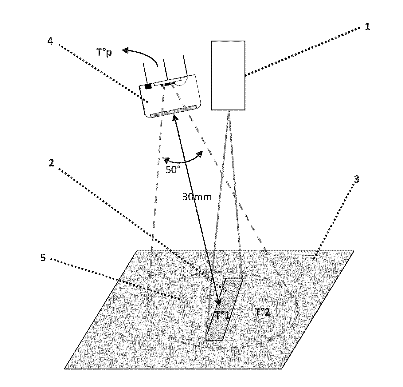
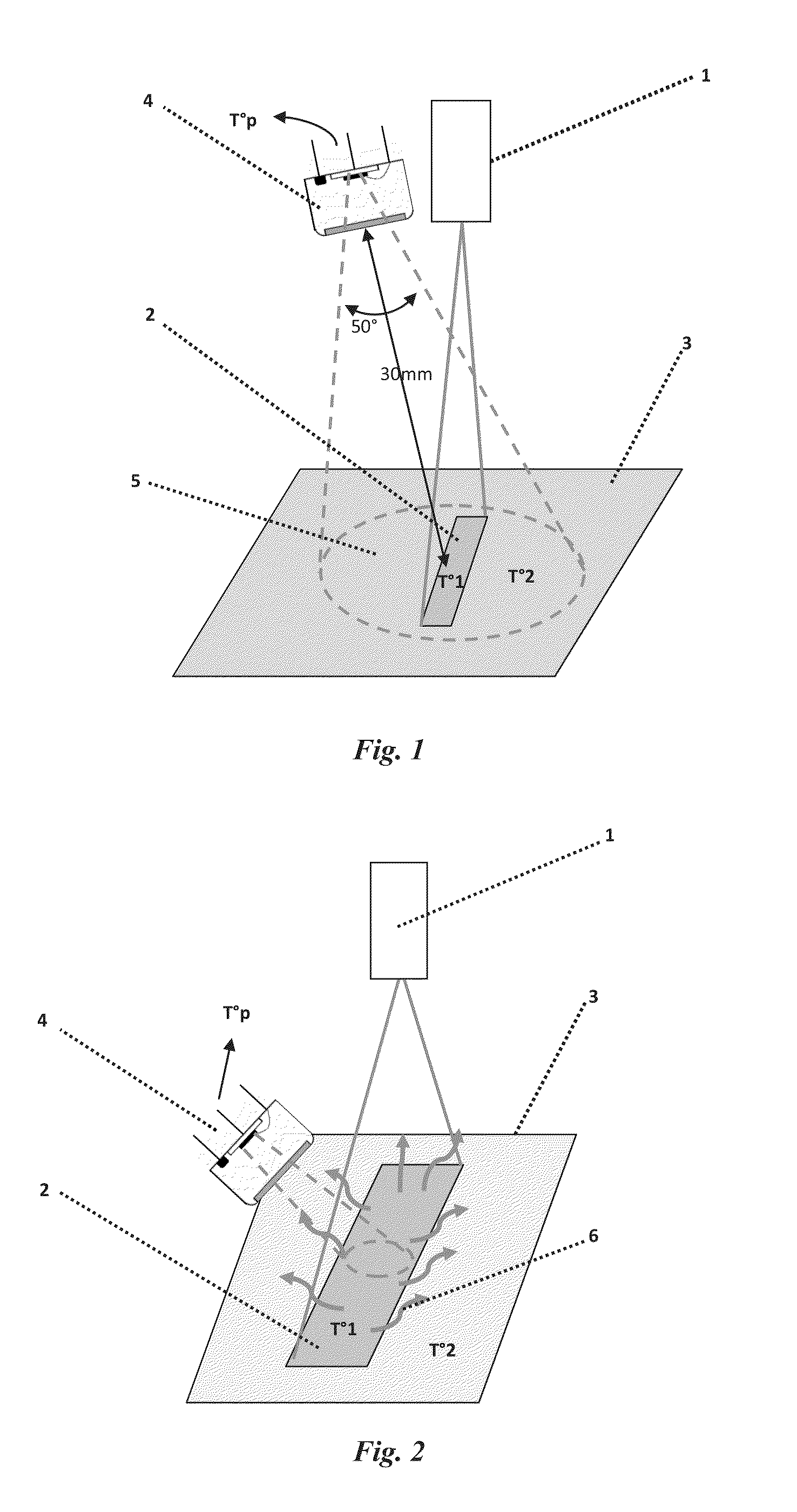
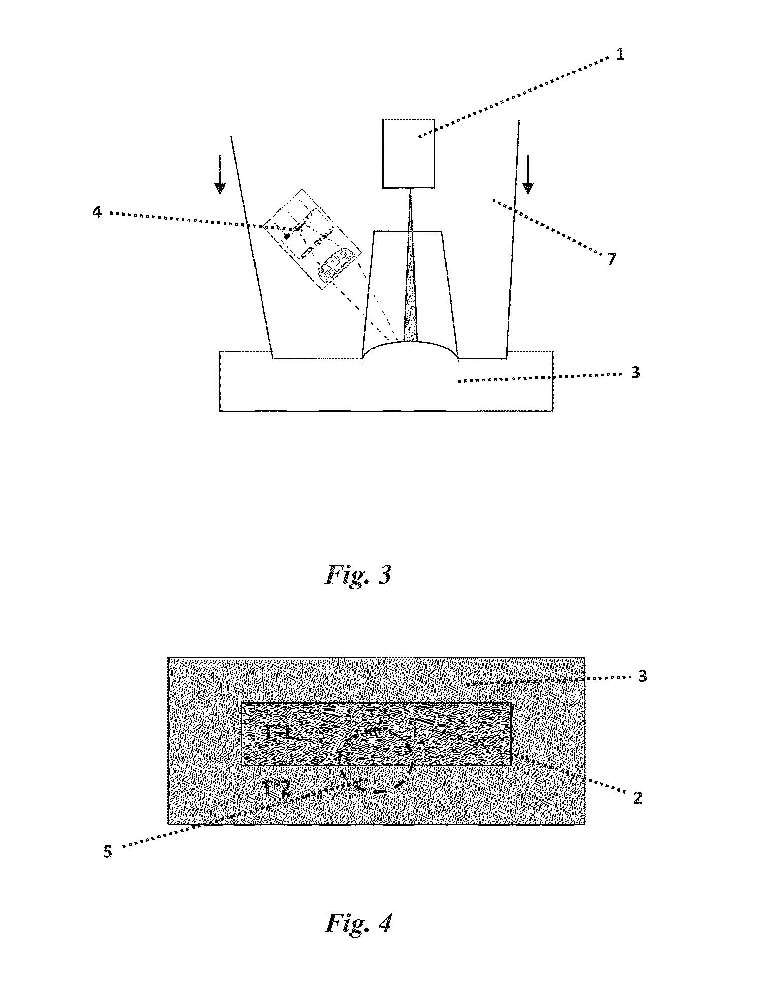
A dermatological treatment device using a light beam, includes: a laser source (1) suitable for directing a laser beam onto at least one zone (2) of the area of skin to be treated, a contactless measurement unit sensitive to radiation according to temperature, of the temperature of a skin area corresponding to the area of skin being treated, and a unit for controlling (13) the laser source via the measurement unit, the device being characterised by the fact that the contactless measurement unit includes an infrared sensor (4) and an objective lens (20) suitable for focusing the field of view (5) of the infrared sensor such that the area of skin contained within the field of view (5) is fully included in the area of skin (2) being treated by the device.

Description

FIELD OF THE INVENTION[0001]This invention concerns a device for dermatological treatment using a laser beam, preferably a laser beam having a wavelength from from 1.1 to 1.6 μm such as 1.21 μmPRIOR ART[0002]It is known via document WO 2009 / 071592, that a device exists for perioperative and post-operative treatment of surgical wounds. This device uses a laser source with a wavelength from 0.6 μm to 2.5 μm, the beam of which is shaped such that, when the laser radiates the skin, energy distribution over the area to be treated is homogenous. More specifically, the beam is shaped in the form of a rectangle in order to match the geometry of an incision, the incision then being treated in several sections of a size equalling the length of the rectangle formed by the laser beam.[0003]The difficulty with this device lies in the fact that the power of the laser and the length of exposure for each section must be determined in order to heat the edges of the incisions to a temperature that mu...

Claims


Application Information

Patent Timeline
IPC IPC(8): A61N5/067
CPCA61B18/203A61B2017/00084A61B2018/00452A61N2005/0659A61B2018/00642A61N5/0616A61B2018/0047
Inventor GIRAUD, SYLVAINGOSSE, ALBANCORNIL, ALAINPERONNE, PATRICK
Owner LABORATOIRE URGO
Learn More