
Pulsed plasma chamber in dual chamber configuration

a plasma chamber and dual chamber technology, applied in the field of pulsed plasma chamber configuration, can solve the problems of plasma re-ignition, plasma re-ignition, and current pulsed rf plasma technology does not provide control of afterglow plasma,

Active Publication Date: 2016-05-26
LAM RES CORP
View PDF19 Cites 18 Cited by
  • Summary
  • Abstract
  • Description
  • Claims
  • Application Information

AI Technical Summary

Benefits of technology

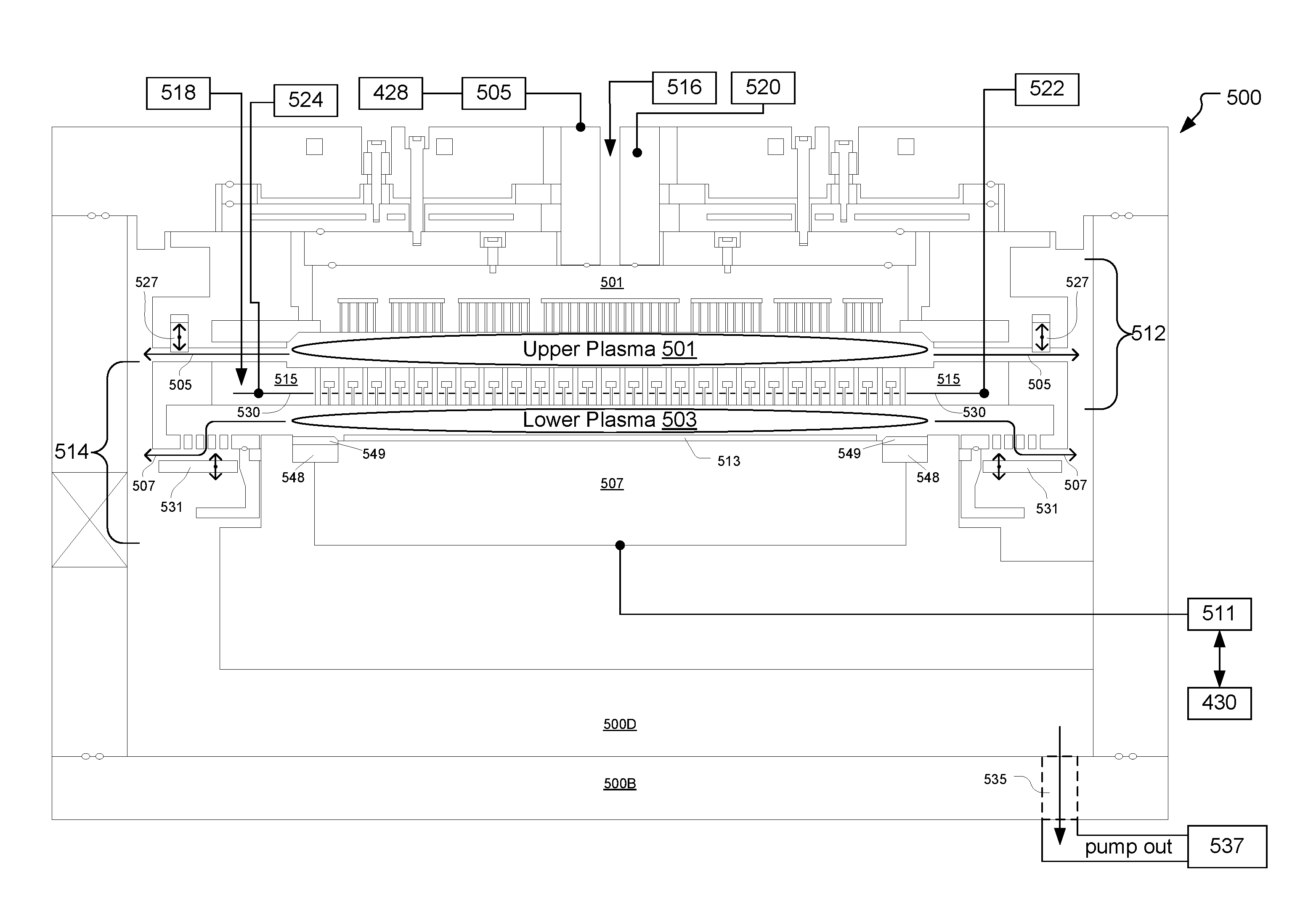
This patent describes a wafer processing apparatus with two chambers separated by a plate that allows for control of the flow of species during operation. The apparatus includes a CW controller, a pulse controller, and a system controller. The CW controller sets the parameters for the first RF power source, the pulse controller sets the parameters for the second and third RF signals, and the system controller transfers these parameters to regulate the flow of species from the top chamber to the bottom chamber through the plate. This flow of species assists in control of negative ion density during the afterglow period and helps to re-strike the plasma in the bottom chamber during the ON period. Overall, this patent presents a technical solution for improving wafer processing in a chamber configuration with a plate for fluid connection between chambers.

Problems solved by technology

Unfortunately, chemistry dissociation and radical formation are coupled to ion production and plasma density and often do not work in concert to achieve the desired plasma processing conditions.
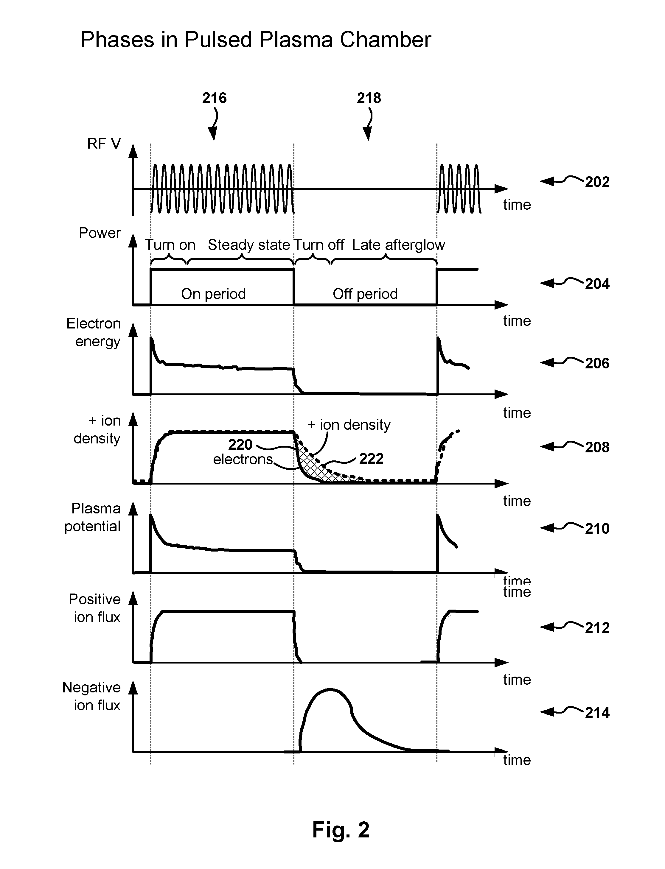
The current pulsed RF plasma technology does not provide control of the afterglow plasma during the RF OFF period when the plasma shuts off.
The charged species dynamics determines the distribution of charges inside the chamber and, therefore, its etching properties, but unfortunately these dynamics and fluxes of charged species are mostly uncontrolled.
Another problem with pulsed plasma technology is plasma re-ignition when the RF power turns on.
If the plasma and the afterglow are extinguished completely during the RF OFF period, re-striking the plasma requires high RF voltage levels.
Further, there can be trouble with RF issues, especially when operating at low gas pressures.

Method used


Image

  • Pulsed plasma chamber in dual chamber configuration
  • Pulsed plasma chamber in dual chamber configuration
  • Pulsed plasma chamber in dual chamber configuration

Examples


Embodiment Construction

[0029]The following embodiments provide systems, methods, and computer programs for processing a semiconductor substrate in a pulsed plasma chamber in a dual chamber configuration. It will be apparent, that the present embodiments may be practiced without some or all of these specific details. In other instances, well known process operations have not been described in detail in order not to unnecessarily obscure the present embodiments.

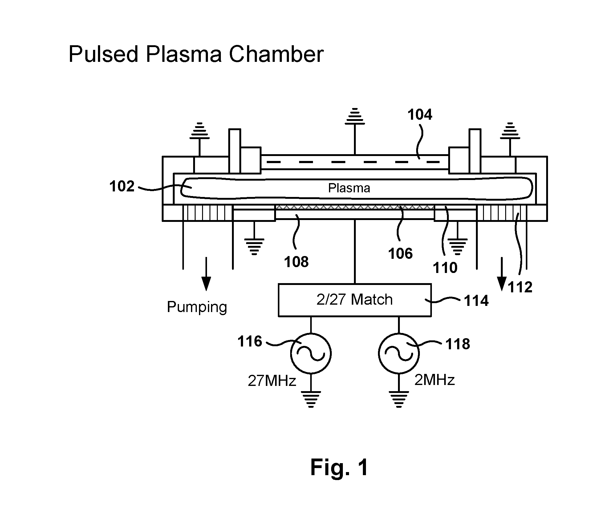
[0030]FIG. 1 shows an etching chamber, according to one embodiment. Exciting an electric field between two electrodes is one of the methods to obtain RF gas discharge in an etching chamber. When an oscillating voltage is applied between the electrodes, the discharge obtained is referred to as a capacitive coupled plasma (CCP) discharge.

[0031]Plasma can be created utilizing stable feedstock gases to obtain a wide variety of chemically reactive by-products created by the dissociation of the various molecules caused by electron-neutral collisions. The c...


PUM


Abstract

Embodiments for processing a substrate in a pulsed plasma chamber are provided. A processing apparatus with two chambers, separated by a plate fluidly connecting the chambers, includes a continuous wave (CW) controller, a pulse controller, and a system controller. The CW controller sets the voltage and the frequency for a first radio frequency (RF) power source coupled to a top electrode. The pulse controller is operable to set voltage, frequency, ON-period duration, and OFF-period duration for a pulsed RF signal generated by a second RF power source coupled to the bottom electrode. The system controller is operable to set parameters to regulate the flow of species between the chambers to assist in the negative-ion etching, to neutralize excessive positive charge on the wafer surface during afterglow in the OFF period, and to assist in the re-striking of the bottom plasma during the ON period.

Description

CLAIM OF PRIORITY[0001]This application is a Divisional application of U.S. patent application Ser. No. 13 / 227,404, filed on Sep. 7, 2011, and entitled, “Pulsed Plasma Chamber in Dual Chamber Configuration.” The disclosure of this related application is incorporated herein by reference for all purposes.CROSS REFERENCE TO RELATED APPLICATIONS[0002]This application is related to U.S. patent application Ser. No. 12 / 850,552, filed on Aug. 4, 2010, entitled “Plasma Processing Chamber with Dual Axial Gas Injection and Exhaust”; U.S. patent application Ser. No. 12 / 850,559, filed on Aug. 4, 2010, entitled “Dual Plasma Volume Processing Apparatus for Neutral / Ion Flux Control”; U.S. patent application Ser. No. 13 / 188,421, filed Jul. 21, 2011, and entitled “Negative Ion Control For Dielectric Etch”, all of which are incorporated herein by reference.BACKGROUND[0003]1. Field of the Invention[0004]The present invention relates to methods, systems, and computer programs for dielectric etching of a...

Claims


Application Information

Patent Timeline
Patent Type & Authority Applications(United States)
IPC IPC(8): H01J37/32H01L21/67H01L21/311
CPCH01J37/32146H01L21/31116H01J2237/3341H01J37/32825H01L21/67069H01J37/32091H01J37/32357
Inventor MARAKHTANOV, ALEXEIDHINDSA, RAJINDERHUDSON, ERICBAILEY, III, ANDREW D.
Owner LAM RES CORP
Learn More