
Phased array antenna

a phased array and antenna technology, applied in the direction of leaky-waveguide antennas, particular array feeding systems, linear waveguide fed arrays, etc., can solve the problems of additive and destructive addition of radiated waves, limited application,

Inactive Publication Date: 2016-05-19
FRAUNHOFER GESELLSCHAFT ZUR FOERDERUNG DER ANGEWANDTEN FORSCHUNG EV
View PDF2 Cites 56 Cited by
  • Summary
  • Abstract
  • Description
  • Claims
  • Application Information

AI Technical Summary

Benefits of technology

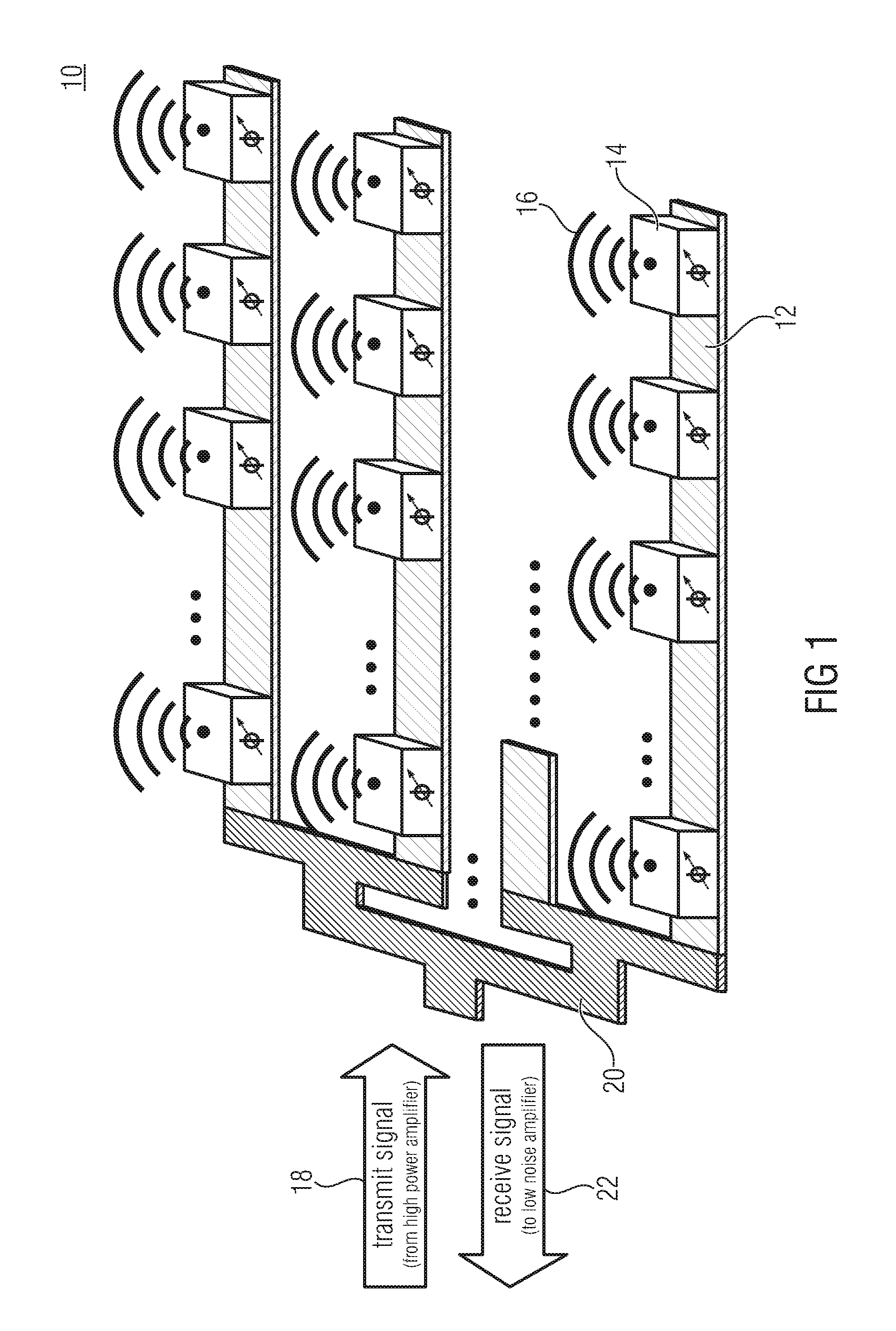
The present invention provides a solution for improving the placement and control of radiating elements in a wireless network. By connecting each radiating element to multiple controllable elements, the original problem of finding suitable settings for each element at the location of the radiating element is transformed into finding suitable settings for each group of controllable elements connected to the radiating element. This provides flexibility in the placement of the radiating elements and results in improved efficiency and control over the wireless network.

Problems solved by technology

Besides satellite communications, the same technical problems exist also for many other communication systems, e.g. terrestrial, space or airborne, where in general high antenna gain improves the signal to noise ratio, while antenna directivity in the direction of propagation helps to mitigate (isolate from) eventually interfering signals from other sources.
However, due to their relatively high price (manufacturing costs, number and quality of components) and power consumption their application is limited to niche markets and applications, e.g. tracking receivers, military applications.
Feeding each of these radiating elements along the row with an identical, but phase shifted signal results in additive and destructive addition of the radiated waves.

Method used


Image

  • Phased array antenna
  • Phased array antenna
  • Phased array antenna

Examples


Embodiment Construction

[0049]Equal or equivalent elements or elements with equal or equivalent functionality are denoted in the following description by equal or equivalent reference numerals.

[0050]In the following description, a plurality of details are set forth to provide a more thorough explanation of embodiments of the present invention. However, it will be apparent to one skilled in the art that embodiments of the present invention may be practiced without these specific details. In other instances, well-known structures and devices are shown in block diagram form rather than in detail in order to avoid obscuring embodiments of the present invention. In addition, features of the different embodiments described hereinafter may be combined with each other, unless specifically noted otherwise.

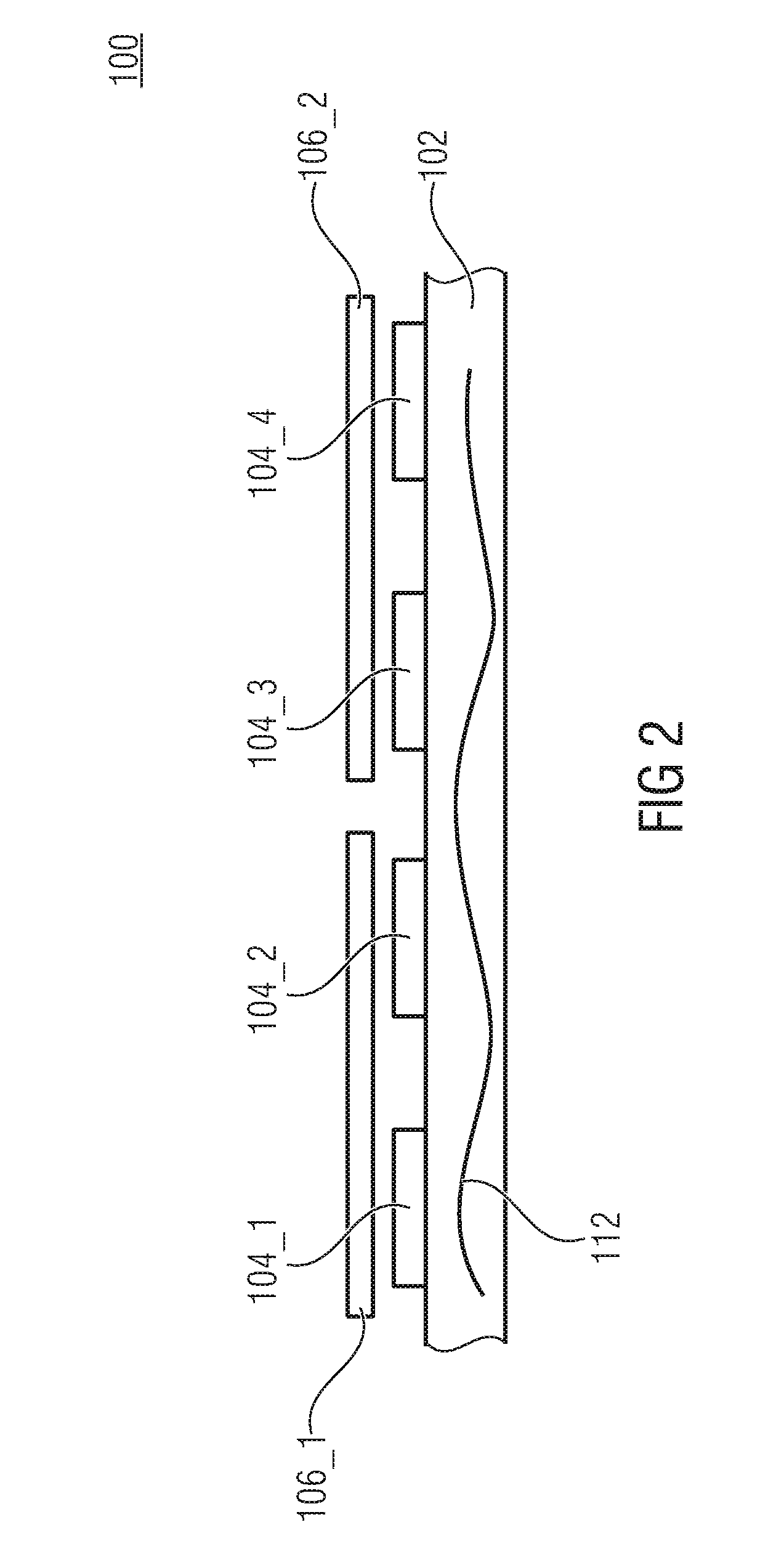
[0051]FIG. 2 shows a side-view of a phased array antenna 100 according to an embodiment. The phased array antenna 100 comprises a feed structure 102 adapted to guide an electromagnetic wave 112, a plurality of con...


PUM


Abstract

Embodiments provide a phased array antenna including a feed structure adapted to guide an electromagnetic wave, a plurality of controllable elements coupled to the feed structure and a plurality of radiating elements, wherein each of the radiating elements is coupled to at least two of the plurality of controllable elements.

Description

CROSS-REFERENCE TO RELATED APPLICATIONS[0001]This application claims priority from European Patent Application No. 14188667.1, which was filed on Oct. 13, 2014, and is incorporated herein in its entirety by reference.BACKGROUND OF THE INVENTION[0002]Embodiments relate to a phased array antenna. Further embodiments relate to a method for operating a phased array antenna. Some embodiments relate to a phased array with dedicated radiating elements.[0003]To receive communication signals from or to transmit communication signals to a satellite, antennas with significant effective gain and directivity are necessitated. Effective gain (e.g. compared to a 0 dB omni-directional antenna) is needed to compensate for the propagation losses through free space and the atmosphere. Directivity (pointing) is necessitated to discriminate the wanted signal from other signals received or transmitted on the same frequency but from / to different orbital locations.[0004]Besides satellite communications, th...

Claims


Application Information

Patent Timeline
IPC IPC(8): H01Q3/36H01Q13/00H01Q3/24
CPCH01Q3/36H01Q13/00H01Q3/247H01Q21/0043H01Q21/005H01Q21/0075H01Q13/28H01Q13/18
Inventor LEYH, MARTINSCHUEHLER, MARIOSCHLICHT, MICHAELMAYER, FRANK
Owner FRAUNHOFER GESELLSCHAFT ZUR FOERDERUNG DER ANGEWANDTEN FORSCHUNG EV
Learn More