Testing system for drive-train

Active Publication Date: 2016-05-19
MEIDENSHA ELECTRIC MFG CO LTD
View PDF0 Cites 12 Cited by
  • Summary
  • Abstract
  • Description
  • Claims
  • Application Information

AI Technical Summary

Benefits of technology

The testing system in this patent invention allows for the simulation of a virtual differential device by calculating the speed values of virtual tires and the torque values of the virtual vehicle. This system can be used in an I-shaped testing system with a single dynamometer. Additionally, the system includes an estimated braking torque value to better represent the behavior of the braking device during the testing process. The technical effects of the invention include the ability to simulate different road surfaces and the ability to reproduce a behavior during braking.

Problems solved by technology

However, in reality, there are road surface conditions, such as a snowy surface or an icy surface on which the tire easily slips.
Document 1, it is difficult to reproduce a state in which the tire slips on such a road surface.

Method used


Image

  • Testing system for drive-train
  • Testing system for drive-train
  • Testing system for drive-train

Examples


first embodiment

[0036]A drive train testing system 1 according to a first embodiment of the invention will be described with reference to the drawings.

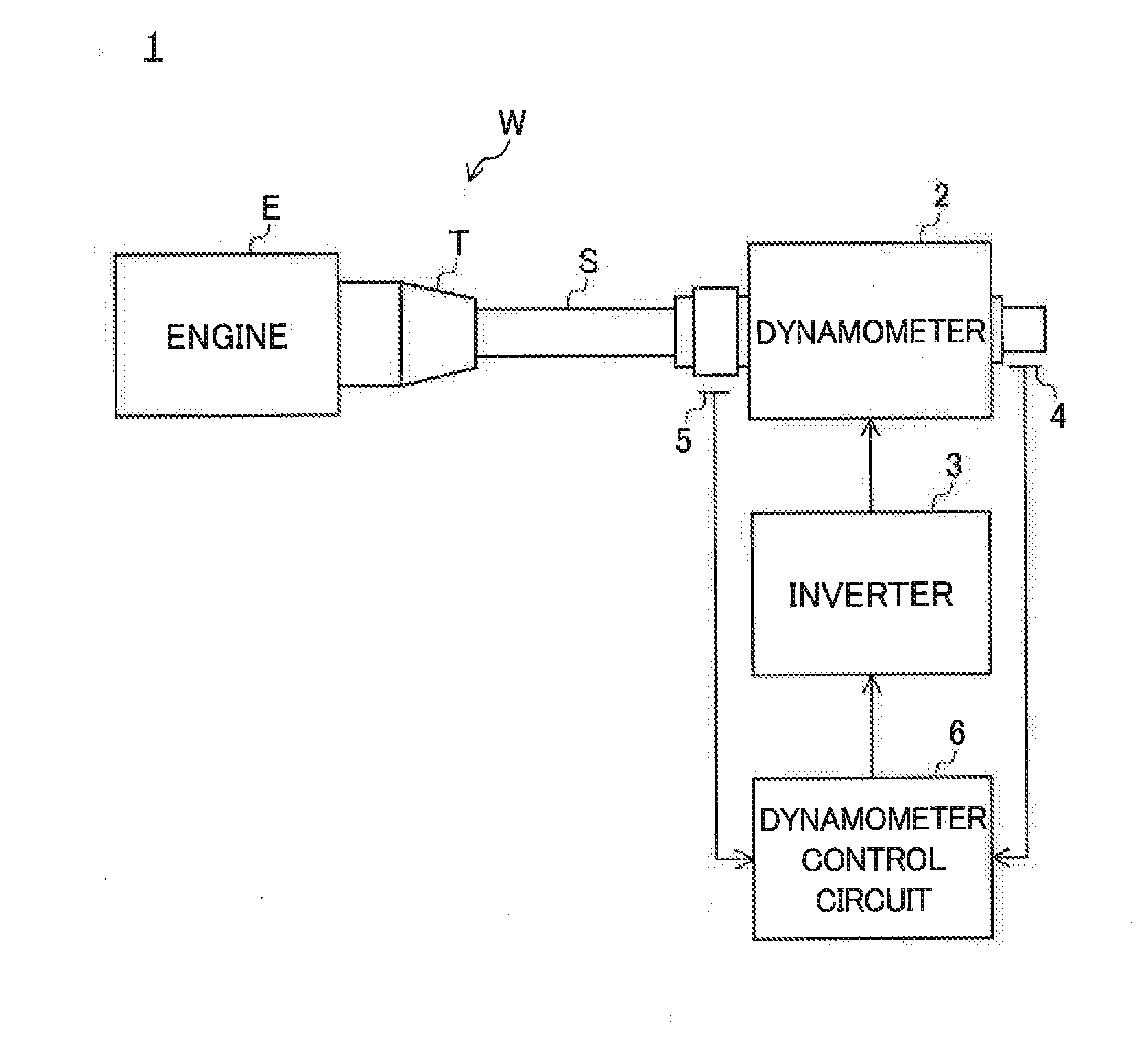
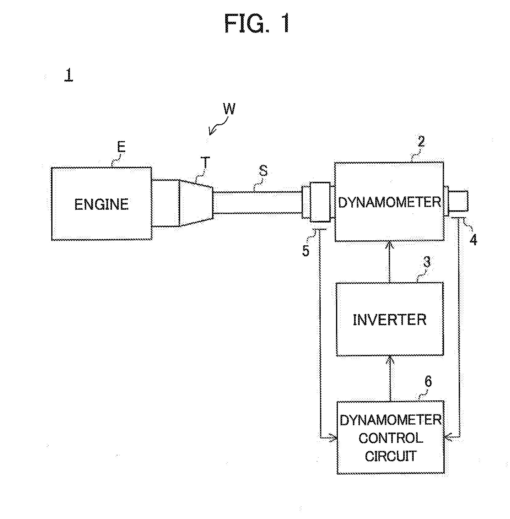
[0037]FIG. 1 is a schematic diagram illustrating the configuration of the testing system 1 of the embodiment. As shown in FIG. 1, the testing system 1 is a so-called I-shaped system that uses a drive train including an engine E, a transmission T, and a propeller shaft S and not including a differential gear (a differential device) as a test piece W.

[0038]The testing system 1 includes a dynamometer 2 coaxially connected to a propeller shaft S, an inverter 3 supplying electric power to the dynamometer 2, an encoder 4 detecting a rotation speed of the dynamometer 2, an axial torque meter 5 detecting an axial torque of the propeller shaft S, a dynamometer control circuit 6 controlling the dynamometer 2 based on output signals of the encoder 4 and the axial torque meter 5, and an engine control device (not shown) controlling the engine E. In the testing s...

second embodiment

[0061]A drive train testing system 1A according to a second embodiment of the invention will be described with reference to the drawings.

[0062]FIG. 5 is a schematic diagram illustrating the configuration of the testing system 1A of the embodiment. In the following description of the testing system 1A, the same reference numerals will be given to the same components as the testing system 1 of the first embodiment, and a detailed description thereof will be omitted. The testing system 1A is different from the testing system 1 of the first embodiment in that a braking device 7A decelerating the rotation of the propeller shaft S is further provided and the dynamometer control circuit 6A has a different configuration.

[0063]The braking device 7A decelerates the rotation of the propeller shaft S by clamping a brake rotor provided in the dynamometer 2 side of the propeller shaft S using a brake caliper (not shown).

[0064]FIG. 6 is a block diagram illustrating the configuration of the dynamom...

third embodiment

[0071]A drive train testing system 1B according to a third embodiment of the invention will be described with reference to the drawings.

[0072]FIG. 8 is a block diagram illustrating the configuration of a dynamometer control circuit 6B of the testing system 1B. In the following description of the testing system 1B, the same reference numerals will be given to the same components as the testing system 1 of the first embodiment, and the detailed description thereof will be omitted. The dynamometer control circuit 6B is different from the dynamometer control circuit 6 of FIG. 2 in that a left braking torque calculation unit 68LB and a right braking torque calculation unit 68RB are further provided and the left tire speed calculation unit 62LB and the right tire speed calculation unit 62RB have a different configuration.

[0073]The left braking torque calculation unit 68LB calculates a left braking torque value DBl generated by the operation of the virtual left braking device provided at t...


PUM


Abstract

Provided is a testing system which is able to reproduce road surfaces in different states between both right and left tires. A testing system is provided with: a tire speed calculation unit which calculates virtual left and right tire speed values; a vehicle speed calculation unit which calculates a virtual vehicle speed value; a vehicle drive torque calculation unit which calculates left and right vehicle drive torque values; a differential torque calculation unit which calculates left and right differential torque values; and a speed control device which outputs a torque current command signal such that a deviation between a speed command value and a value detected by an encoder is eliminated. The tire speed calculation unit calculates the tire speed value on the basis of the differential torque values and the vehicle drive torque values.

Description

TECHNICAL FIELD[0001]The present invention relates to a drive train testing system.BACKGROUND ART[0002]A drive train generally corresponds to a plurality of devices used to transmit energy generated by an engine to drive wheels, and includes an engine, a clutch, a transmission, a drive shaft, a propeller shaft, a differential gear, and drive wheels. In a drive train testing system, the durability performance or the quality of a drive train is evaluated while an appropriate load torque is applied to an output shaft in a manner so that the transmission is actually driven by an engine and a dynamometer connected to an output shaft thereof is subjected to an electric inertia control.[0003]In many cases, in the electric inertia control employed in such a testing system, only a single inertia amount corresponding to a vehicle inertia moment can be set as shown in, for example, Patent Document 1. This simulation model is assumed under the condition that the vehicle normally travels on a ro...

Claims


Application Information

Patent Timeline
IPC IPC(8): G01M17/007
CPCG01L3/02G01M15/044G01L5/26G01L3/24G01M17/007B60C23/061B60C99/006G01M13/025
Inventor AKIYAMA, TAKAOSAWADA, YOSHIMASA
Owner MEIDENSHA ELECTRIC MFG CO LTD
Why Eureka
Try Eureka