
Subsea fluid processing system with intermediate re-circulation

a technology of fluid processing system and fluid flow, which is applied in the direction of machines/engines, mechanical equipment, and well accessories, etc., can solve the problems of gas slugs, high gvf of pumps receiving production fluids with high gvf, and damage to pumps. , to achieve the effect of reducing a gas volume fraction (gvf), efficient handling of production fluids, and high gas volume fraction

Inactive Publication Date: 2016-05-19
GENERAL ELECTRIC CO
View PDF3 Cites 8 Cited by
  • Summary
  • Abstract
  • Description
  • Claims
  • Application Information

AI Technical Summary

Benefits of technology

The present invention provides a fluid processing system and method for reducing the gas volume fraction of a production fluid. The system includes a pump with slots for extracting a portion of the multiphase fluid, a reservoir for separating the fluid into liquid and gas phases, and a re-circulation conduit for regulating the flow of the liquid phase back into the pump. The method involves introducing the multiphase fluid into the pump, extracting at least a portion of it, separating it into liquid and gas phases, re-circulating the liquid phase back into the pump, and mixing it with the multiphase fluid to further reduce the gas volume fraction. This results in a compressed multiphase fluid with a reduced gas volume fraction that can be transported to a storage facility.

Problems solved by technology

Generally, gas slugs occur due to flow instability of multiple phases of the production fluids.
Such flow instability may occur in pipelines deployed for moving the production fluids.
Pumps receiving such production fluids with high GVF may be damaged thereby.
However, such re-circulation of the liquid phase may result in overall pressure losses to the system as the liquid phase at high pressure needs to be throttled to lower pressure before being fed to the inlet tank.
Further, when the pressure is lowered the liquid phase may tend to flash (i.e. convert from a liquid phase to a gaseous phase) which may reduce efficiency.

Method used


Image

  • Subsea fluid processing system with intermediate re-circulation
  • Subsea fluid processing system with intermediate re-circulation
  • Subsea fluid processing system with intermediate re-circulation

Examples


Embodiment Construction

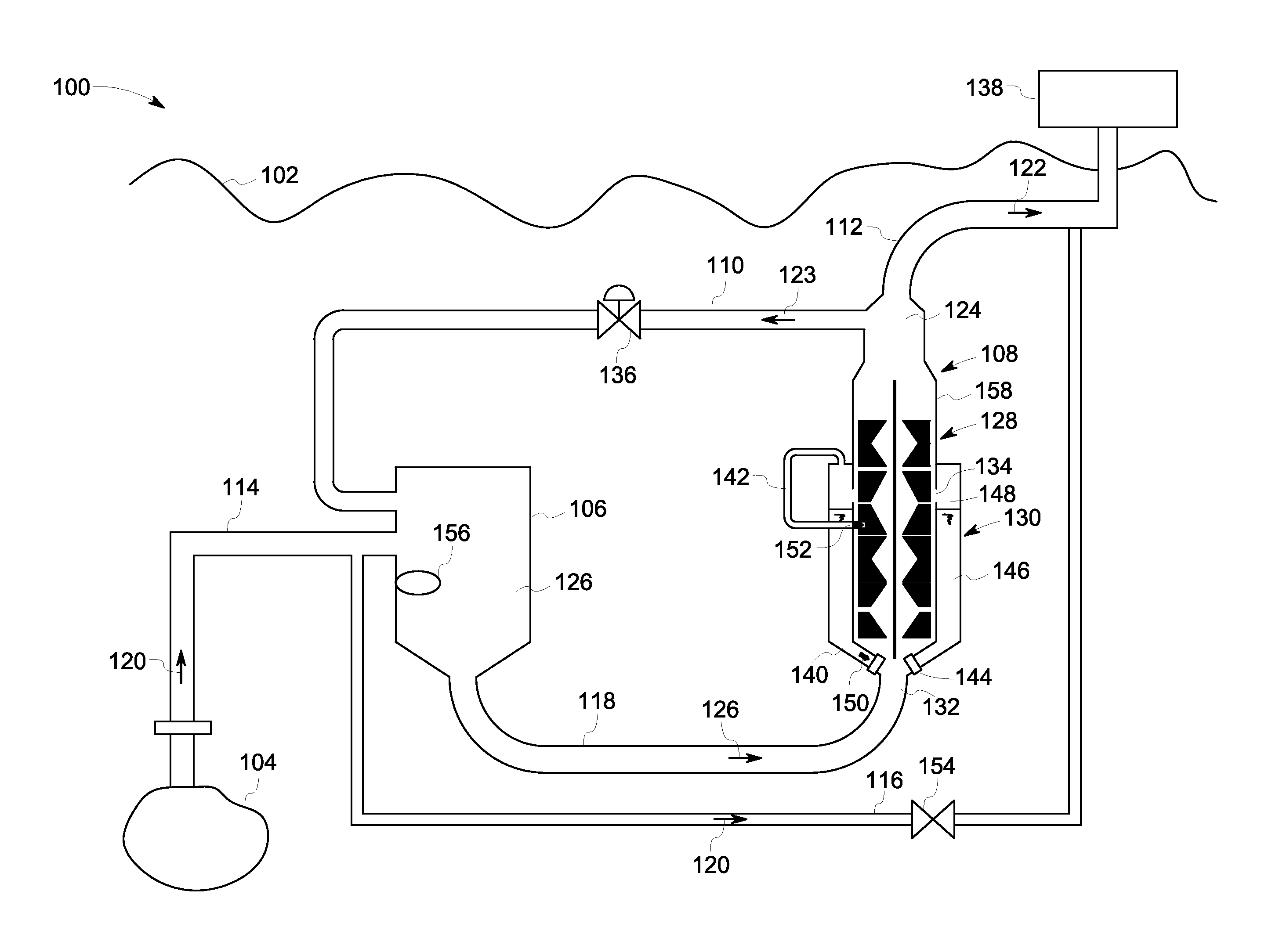
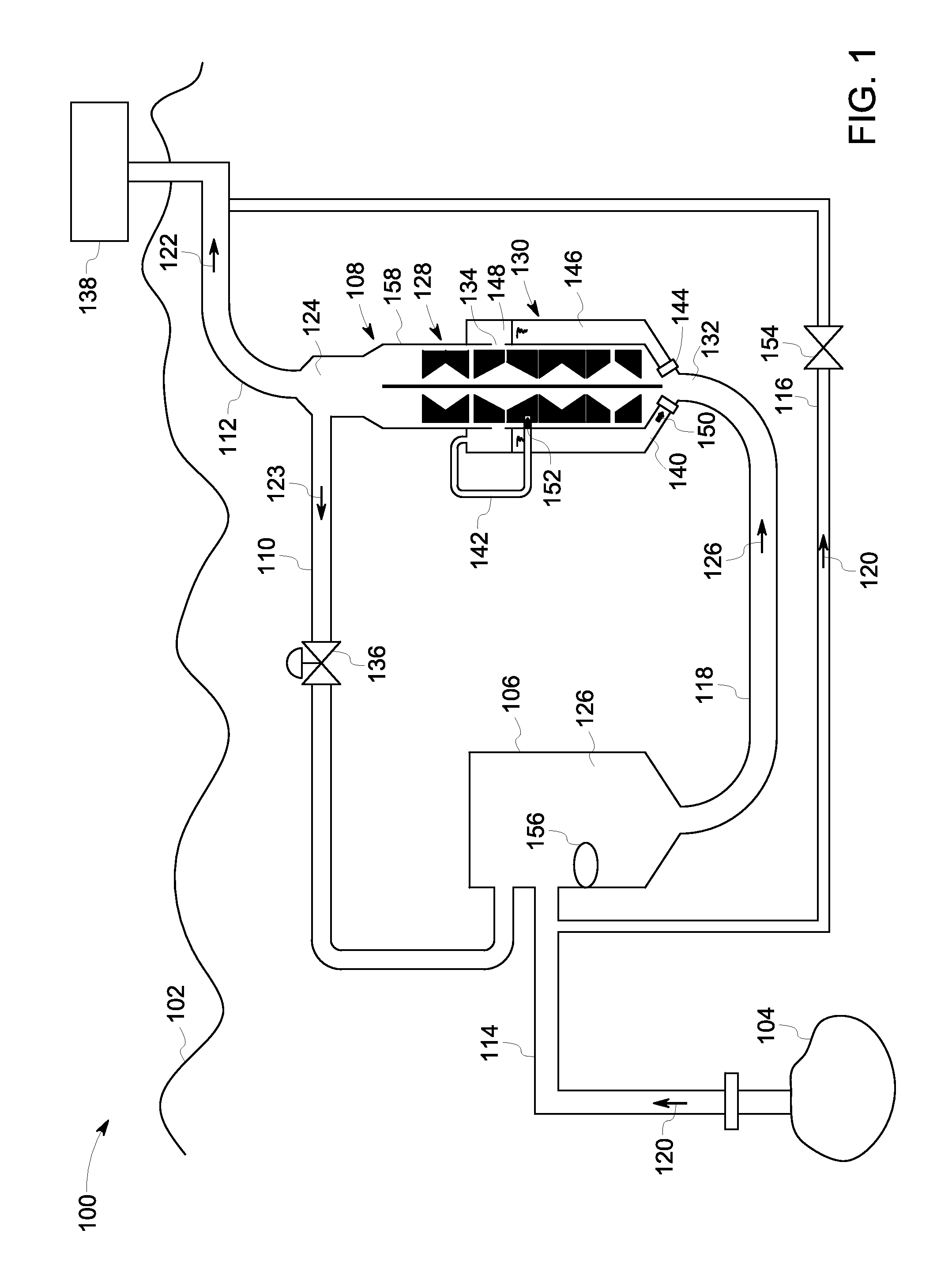
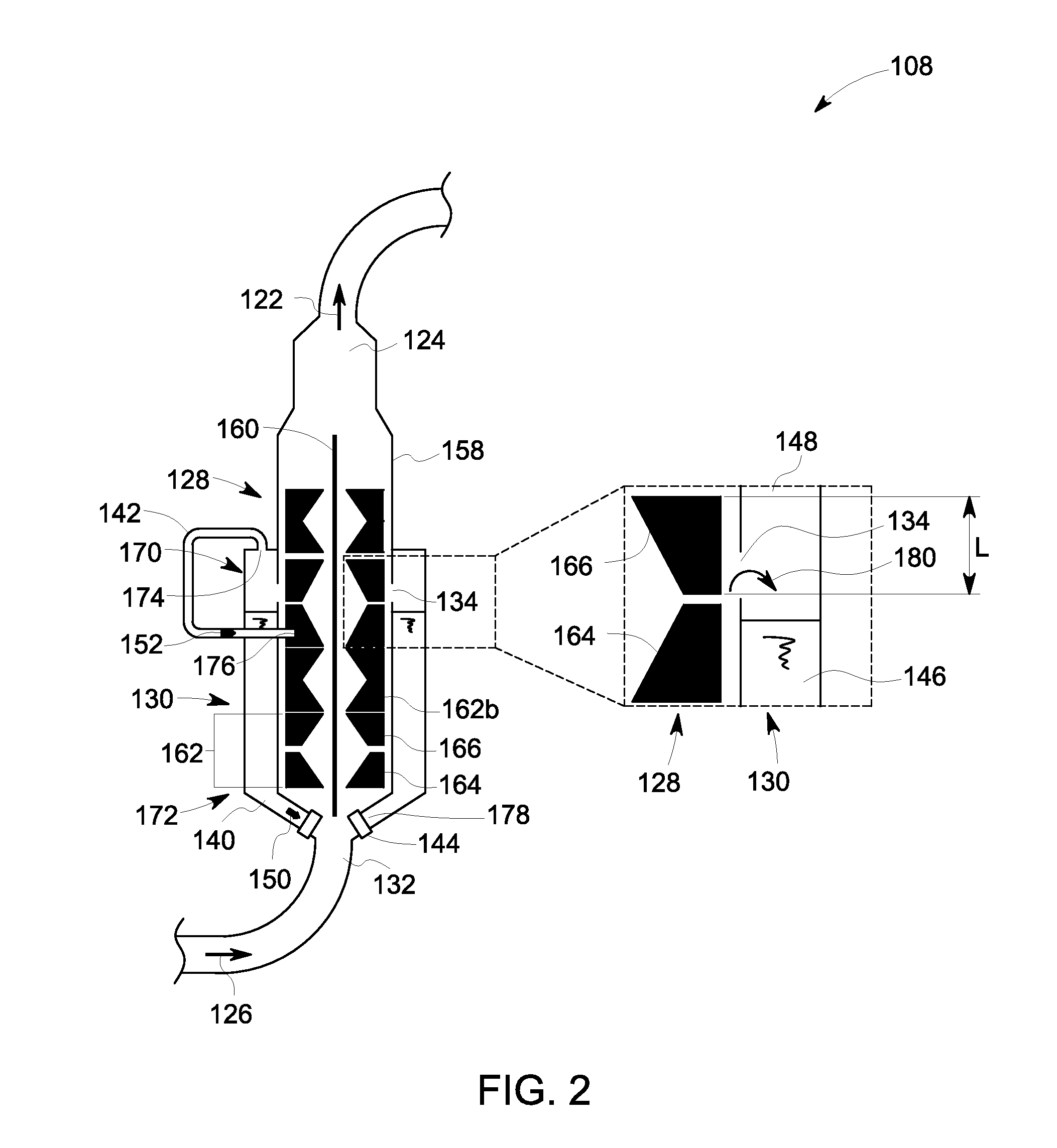
[0027]Embodiments discussed herein disclose new subsea systems for efficiently moving production fluids characterized by high gas volume fraction (GVF) from a hydrocarbon reservoir to a distant fluid storage facility. Specifically, the embodiments disclose an improved fluid processing system for effectively managing the GVF of the production fluids. The fluid processing system of the present invention comprises a pump and a fluid reservoir encompassing a portion of the pump. One or more slots defined in a casing of the pump, are configured to extract a portion of a multiphase fluid flowing in the pump at an intermediate pressure. The one or more slots may be defined in one or more regions of the casing and may have optimal shapes to facilitate extraction of a stagnant portion (flow) of the multiphase fluid without affecting a main flow of the multiphase fluid. A discharge device is coupled to a re-circulation conduit of the fluid reservoir. The discharge device may include one among...


PUM


Abstract

A fluid processing system is provided containing a pump and a fluid reservoir. The pump includes a casing, one or more pump stages, a pump inlet, and a pump outlet. The casing includes one or more slots, with at least one slot configured to extract at least a portion of a multiphase fluid flowing within the pump. The fluid reservoir encompasses at least a portion of the casing and is configured to receive and separate the portion of the multiphase fluid into an extracted liquid phase and an extracted gaseous phase. The fluid reservoir includes a re-circulation conduit disposed proximate to the pump inlet and a discharge device coupled to the re-circulation conduit. The discharge device regulates re-circulation of at least a portion of the extracted liquid phase to the pump via the pump inlet for reducing a gas volume fraction of the multiphase fluid being fed to the pump.

Description

CROSS REFERENCE TO RELATED APPLICATIONS[0001]This application claims priority under 35 U.S.C. §119(e) from Provisional Application No. 62 / 079,125 filed on 13 Nov. 2014, which is incorporated by reference herein in its entirety.BACKGROUND[0002]The present invention relates to fluid processing systems for deployment in a subsea environment, and more particularly to subsea systems capable of handling production fluids characterized by high gas volume fraction (GVF).[0003]Fluid processing systems used for hydrocarbon production in subsea environments typically include pumps configured to boost production fluids from a subsea hydrocarbon reservoir to a distant storage facility. Such pumps are typically designed to operate with production fluids having relatively low gas volume fraction (GVF).[0004]Generally, gas slugs occur due to flow instability of multiple phases of the production fluids. Such flow instability may occur in pipelines deployed for moving the production fluids. Eventuall...

Claims


Application Information

Patent Timeline
Patent Type & Authority Applications(United States)
IPC IPC(8): F04D3/00F04D15/00
CPCF04D15/0005F04D3/00E21B43/01E21B43/36F04D17/14F04D31/00F04D13/10F04D15/0027F04D15/0072
Inventor BECQUIN, GUILLAUMEDU CAUZE DE NAZELLE, RENEMICHELASSI, VITTORIO
Owner GENERAL ELECTRIC CO
Learn More