
Thin planar biological sensor

a biological sensor and planar technology, applied in the field of biological sensors, can solve the problems of affecting the accuracy of biological measurements, the conductivity of conductive glue decaying with time, and the electrodes of biomedical measurement systems also need conductive glu

Inactive Publication Date: 2016-05-12
NAT CHIAO TUNG UNIV
View PDF3 Cites 37 Cited by
  • Summary
  • Abstract
  • Description
  • Claims
  • Application Information

AI Technical Summary

Benefits of technology

The present invention provides a thin planar biological sensor with several technical advantages. Firstly, it solves the conventional issues of measuring electrodes by providing a more flexible and stable sensor. Secondly, it uses flexible measuring electrodes that can perform both instantaneous and extended biological measurements with stable signals. Thirdly, it avoids the use of conductive glue and can measure various biomedical signals. Fourthly, the biological sensor is designed to have excellent adhesion to the subject regardless of their movement. Fifthly, the sensor can be connected to a remote Tx / Rx for further analysis. Overall, the flexible electrodes make better contact with the subject's skin, ensuring efficient measurement.

Problems solved by technology

However, it is well known that wet electrodes have to cooperate with conductive glue, and the conductive glue may cause discomfort or allergy to patients.
Besides, conductivity of the conductive glue decays with time.
Similar to the electrodes of EEG systems, the electrodes of biomedical measurement systems also need conductive glue and have the same drawbacks of wet electrodes.
It is believed that these microstructure-based dry electrodes are kind of invasive measurements, and are likely to fracture and hard to apply to hairy regions of a subject.
Therefore is impaired popularization of dry electrodes.
The conventional bulky and complicated devices should have been out of date.
However, many researches are still impeded by shortage of efficacious and cost-efficient technologies, thereby limiting more and more developments still until now.

Method used


Image

  • Thin planar biological sensor
  • Thin planar biological sensor
  • Thin planar biological sensor

Examples


Embodiment Construction

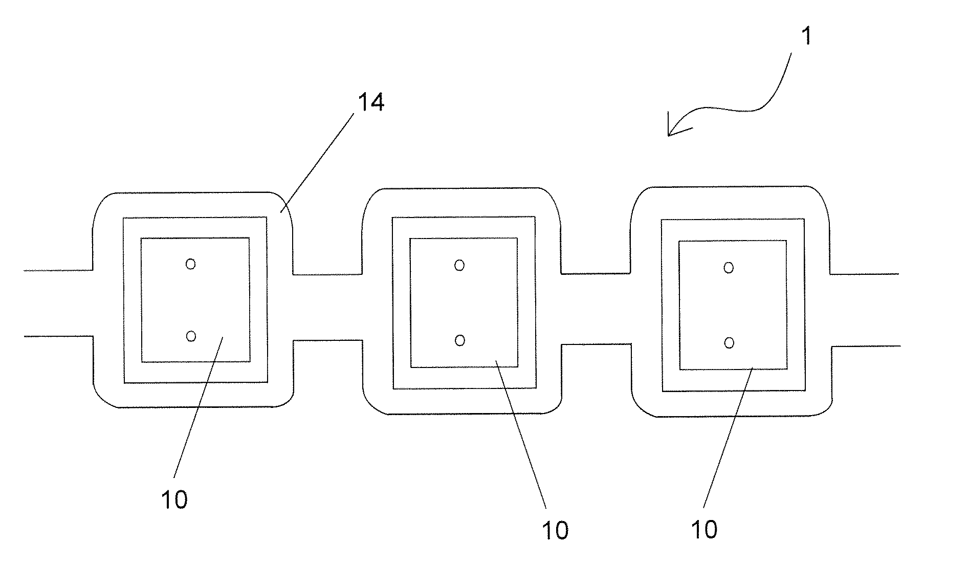
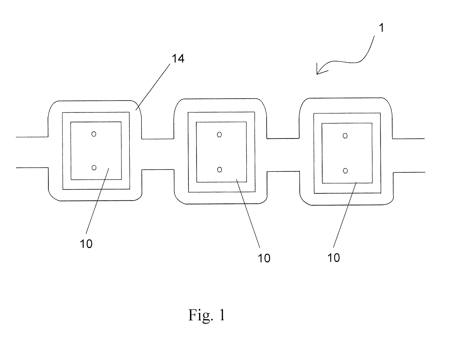
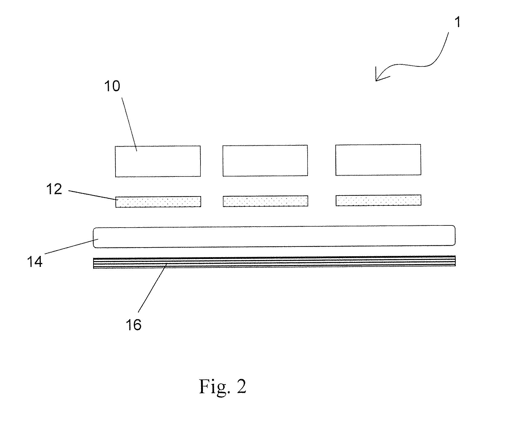
[0028]Refer to FIG. 1 and FIG. 2, which respectively shows a top view and a side view of a thin planar biological sensor according to one embodiment of the present invention. As shown, the thin planar biological sensor 1 comprises at least one flexible electrode 10, at least one conductive plate 12, a buffer layer 14 and a printed circuit board 16, wherein the flexible electrode 10 is made of silicon-silver-based material, that is both bendable, conductive, and non-allergy. According to the present invention, a ratio of the silicon to silver-compound is about 7:3. And, the silver-compound further comprises silver and silicon-dioxide (SiO2), in which a ratio of silver to silicon-dioxide is 1:9. Since the proposed silver-compound has great conductivity, and shows extinct flexibility while combined with SiO2, it helps to make the proposed biological sensor much more flexible and cozy than ever. Therefore, when the thin planar biological sensor of the present invention is placed on a su...


PUM


Abstract

A thin planar biological sensor is provided, comprising at least one flexible electrode used for contacting a subject's skin and measuring biological signal. The flexible electrode is made of silicon-silver-based material, in which a ratio of silicon to silver-compound is about 7:3. A conductive plate is coupled to the flexible electrode. A buffer layer covers the conductive plate and the flexible electrode. A printed circuit board is used to receive the measured biological signal. By employing the novel proposed biological sensor, it is advantageous of measuring biological signals not only EEG signals but also ECG and EMG signals. Besides being thin, planar, flexible and non-allergy attributing a low cost to the proper fabrications makes the proposed sensor characterized with a potential for becoming an important tool of medical measurement.

Description

[0001]This application claims priority for Taiwan patent application no. 103139019 filed on Nov. 11, 2014, the content of which is incorporated by reference in its entirely.BACKGROUND OF THE INVENTION[0002]1. Field of the Invention[0003]The present invention relates to a biological sensor, and more particularly to a thin planar biological sensor which adopts silicon-silver-based conductive material that is both flexible and biologically-compatible as measuring electrodes.[0004]2. Description of the Related Art[0005]Biomedical measurement systems are popular medical apparatuses. Many research papers have been proposed to improve the inconveniences and drawbacks of biomedical measurement systems nowadays. Traditional EEG (electroencephalography) systems normally intend to adopt wet electrodes. However, it is well known that wet electrodes have to cooperate with conductive glue, and the conductive glue may cause discomfort or allergy to patients. Besides, conductivity of the conductive...

Claims


Application Information

Patent Timeline
IPC IPC(8): A61B5/0478A61B5/0496A61B5/0488A61B5/00A61B5/0402
CPCA61B5/0478A61B5/6814A61B5/0006A61B5/0488A61B5/0496A61B5/0402A61B2560/0412A61B2562/0215A61B5/282A61B5/291A61B5/398A61B5/296
Inventor LIN, CHIN-TENGYU, YI-HSINLU, SHAO-WEILIAO, LUN-DE
Owner NAT CHIAO TUNG UNIV
Learn More