
Solar still countercurrent flow system and apparatus

a solar still and countercurrent technology, applied in the direction of distillation separation, chemistry apparatus and processes, separation processes, etc., can solve the problems of three percent of the water considered clean enough to drink, the temperature performance of solar stills is not uniform and consistent, and the lack of food and water in poor countries around the world is limited.

Inactive Publication Date: 2016-05-05
BOARD OF RGT THE UNIV OF TEXAS SYST
View PDF4 Cites 3 Cited by
  • Summary
  • Abstract
  • Description
  • Claims
  • Application Information

AI Technical Summary

Benefits of technology

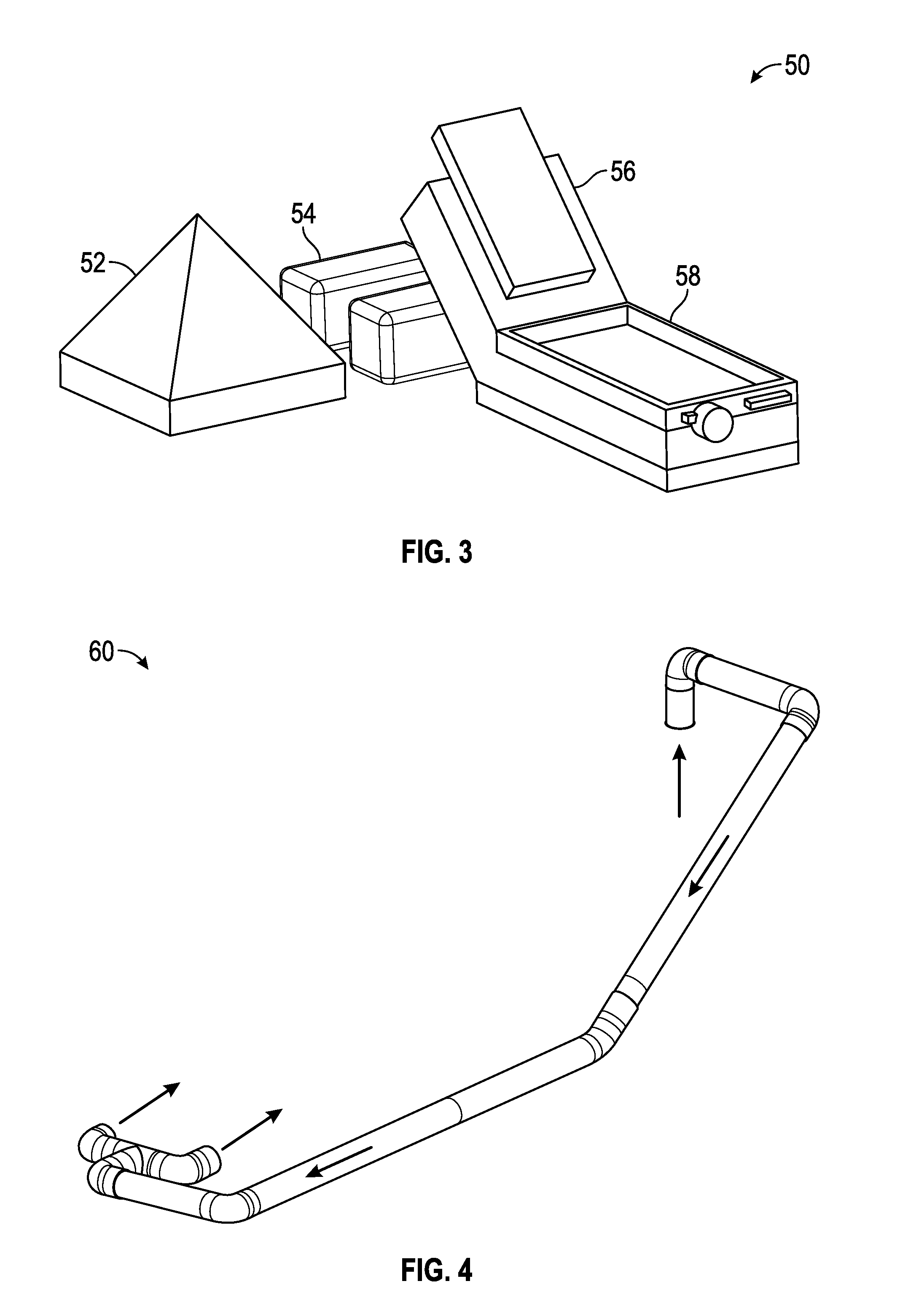
The disclosed embodiments provide an improved solar distillation system with a better cold air return duct that ensures consistent and smooth airflow through the system and improved performance in the solar collector and condenser. The design of the cold air return duct allows for natural buoyancy-driven convection and efficient airflow control through the system. A countercurrent flow system can also be integrated into the solar system without an external return duct. Overall, the solar distillation system with these innovative features is more efficient and effective in desalination and purification of saltwater or brackish water.

Problems solved by technology

More so, impoverished countries around the world have limited means to provide food and water to its inhabitants.
The world has an abundance of water, however, only three percent of it is considered clean enough to drink.
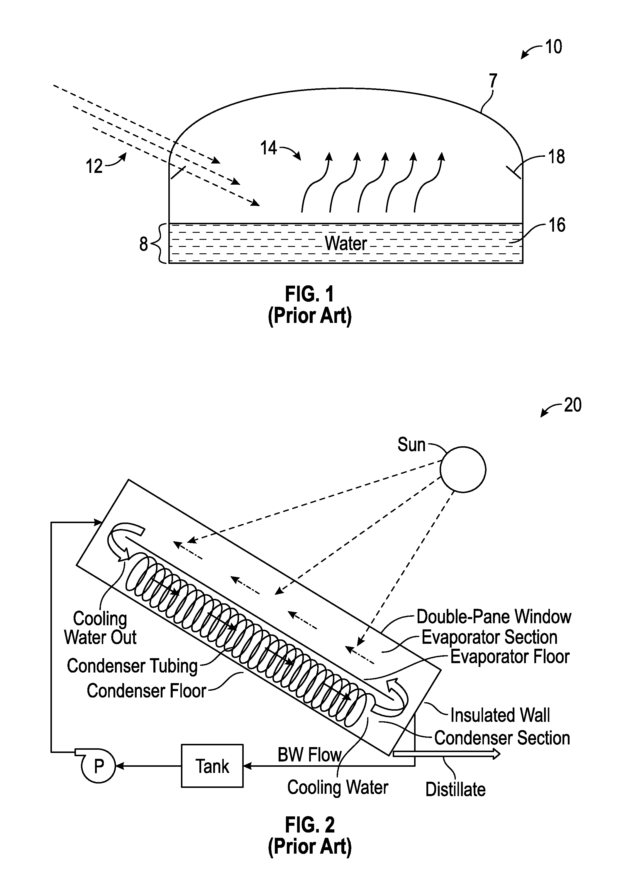
However, solar stills have not been widely employed because the classic still only produces approximately 3 liters per day per square meter of solar capture.
This poses a challenge since the amount of drinking water consumed per person is approximately 2 liters per day.
Reverse osmosis is currently the most popular method of desalinating water, but is energy intensive and has a high operating cost, making it unreasonable for insolvent regions.
As the water evaporates, it leaves behind contaminants such as salt, bacteria, and other substances that compromise the water.

Method used


Image

  • Solar still countercurrent flow system and apparatus
  • Solar still countercurrent flow system and apparatus
  • Solar still countercurrent flow system and apparatus

Examples


Embodiment Construction

[0022]The particular values and configurations discussed in these non-limiting examples can be varied and are cited merely to illustrate one or more embodiments and are not intended to limit the scope thereof.

[0023]Subject matter will now be described more fully hereinafter with reference to the accompanying drawings, which form a part hereof, and which show, by way of illustration, specific example embodiments. Subject matter may, however, be embodied in a variety of different forms and, therefore, covered or claimed subject matter is intended to be construed as not being limited to any example embodiments set forth herein; example embodiments are provided merely to be illustrative. Likewise, a reasonably broad scope for claimed or covered subject matter is intended. Among other things, for example, subject matter may be embodied as methods, devices, components, or systems.

[0024]Throughout the specification and claims, terms may have nuanced meanings suggested or implied in context...


PUM


Abstract

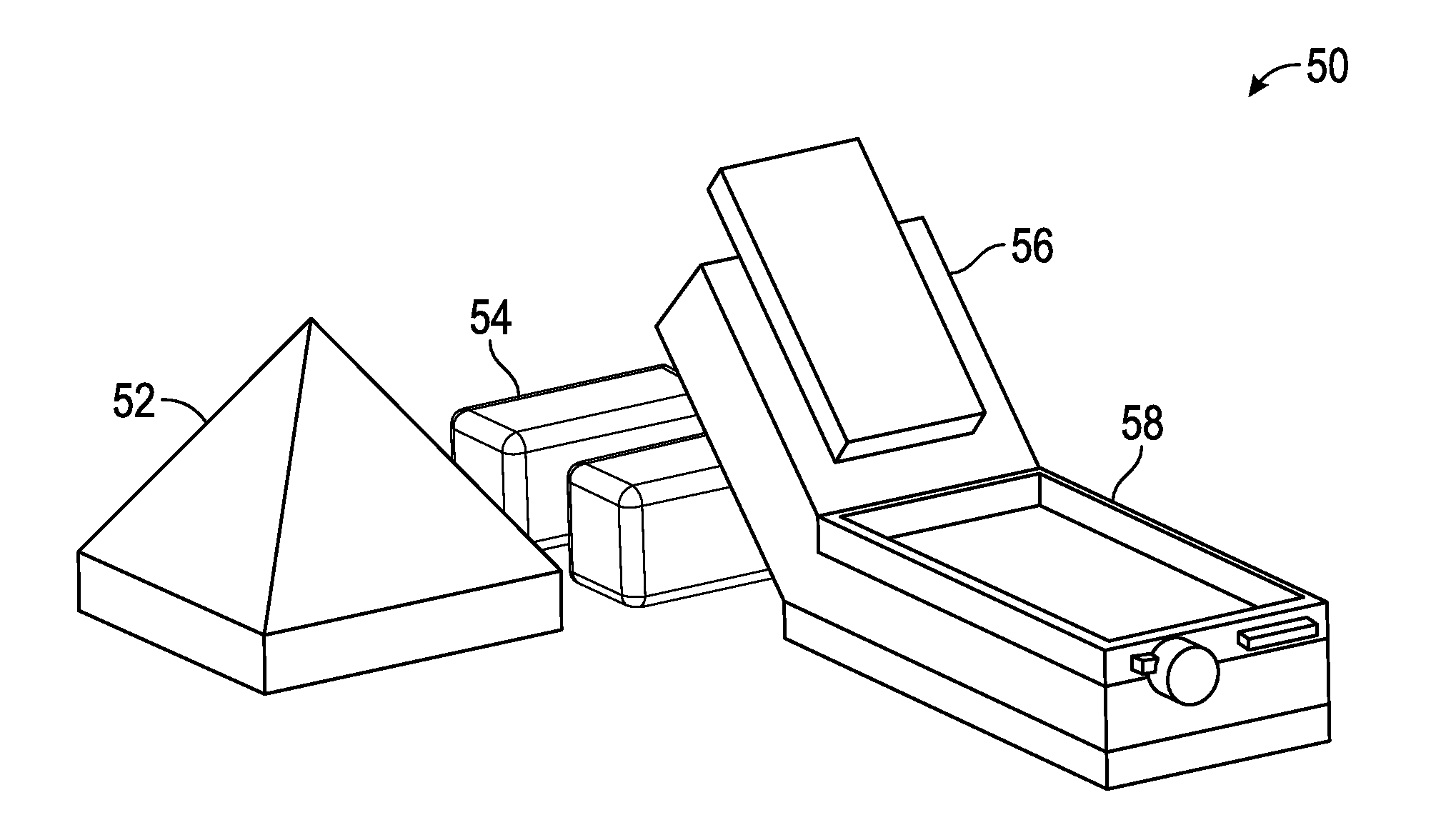
A solar distillation system includes a solar collector located adjacent to a condenser, the condenser located at an angle with respect to the condenser. The solar distillation system further includes a 2nd effect and an insulated portion located between the condenser and the 2nd effect. The solar collector, the condenser, the insulated portion, and the 2nd effect function to desalinate and purify saltwater or brackish water flowing through the solar distillation system.

Description

CROSS-REFERENCE TO PROVISIONAL APPLICATION[0001]This patent application clams priority under 35 U.S.C. 119(e) to U.S. Provisional Patent Application Ser. No. 62 / 074,024, entitled “Solar Still Countercurrent Flow System and Apparatus,” which was filed on Nov. 2, 2014, the disclosure of which is incorporated herein by reference in its entirety.TECHNICAL FIELD[0002]Embodiments are generally related to the field of solar distillation systems and devices.BACKGROUND[0003]The global population is growing and its resource dependency is growing accordingly. More so, impoverished countries around the world have limited means to provide food and water to its inhabitants. The world has an abundance of water, however, only three percent of it is considered clean enough to drink. Desalination technology offers the potential to make use of the world's vast brackish and saline water resources.[0004]Solar distillation is a method of purifying water by harnessing the sun's energy. It is an effective ...

Claims


Application Information

Patent Timeline
IPC IPC(8): C02F1/14C02F1/04
CPCC02F1/14C02F2103/08C02F1/043C02F1/045Y02A20/124Y02A20/142Y02A20/212
Inventor WALKER, WILLIAM S.SAENZ, ADRIANKEMP, HILLERY T.MANFORD, JOHN
Owner BOARD OF RGT THE UNIV OF TEXAS SYST
Learn More