Lighting device

a technology of light source and led lamp, which is applied in the direction of semiconductor devices for light sources, lighting elements, lighting and heating apparatus, etc., can solve the problems of high lumen output, high cost, and limited thermal properties of led lamp concept, and achieve low cost, low thermal resistance, and high availability volume

Active Publication Date: 2016-04-28
SIGNIFY HLDG BV
View PDF14 Cites 2 Cited by
  • Summary
  • Abstract
  • Description
  • Claims
  • Application Information

AI Technical Summary

Benefits of technology

[0004]It is an object of the present invention to at least provide an improved lighting device. It would be advantageous to achieve a lighting device suitable for a retrofit LED lamp at low cost, which has a low thermal resistance, Rth, on system level. It would also be desirable to enable a lighting device which has a high available volume for the driver electronics, and to provide a good optical performance with the possibility of an omni-directional light distribution. These objects are achieved by a lighting device according to the present invention as defined in the appended independent claim. Preferred embodiments are set forth in the dependent claims and in the following description and drawings.

Problems solved by technology

A LED lamp concept for a high intensity, high lumen output, is typically limited by its thermal properties and available space for the driver electronics.

Method used


Image

  • Lighting device
  • Lighting device
  • Lighting device

Examples


Embodiment Construction

[0020]The present invention will now be described more fully hereinafter with reference to the accompanying drawings. The below embodiments are provided by way of example so that this disclosure will be thorough and complete, and will fully convey the scope of the invention to those skilled in the art. Like numbers refer to like elements throughout.

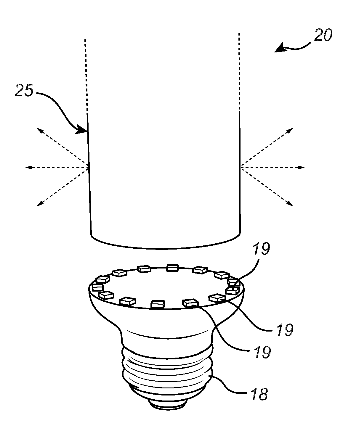
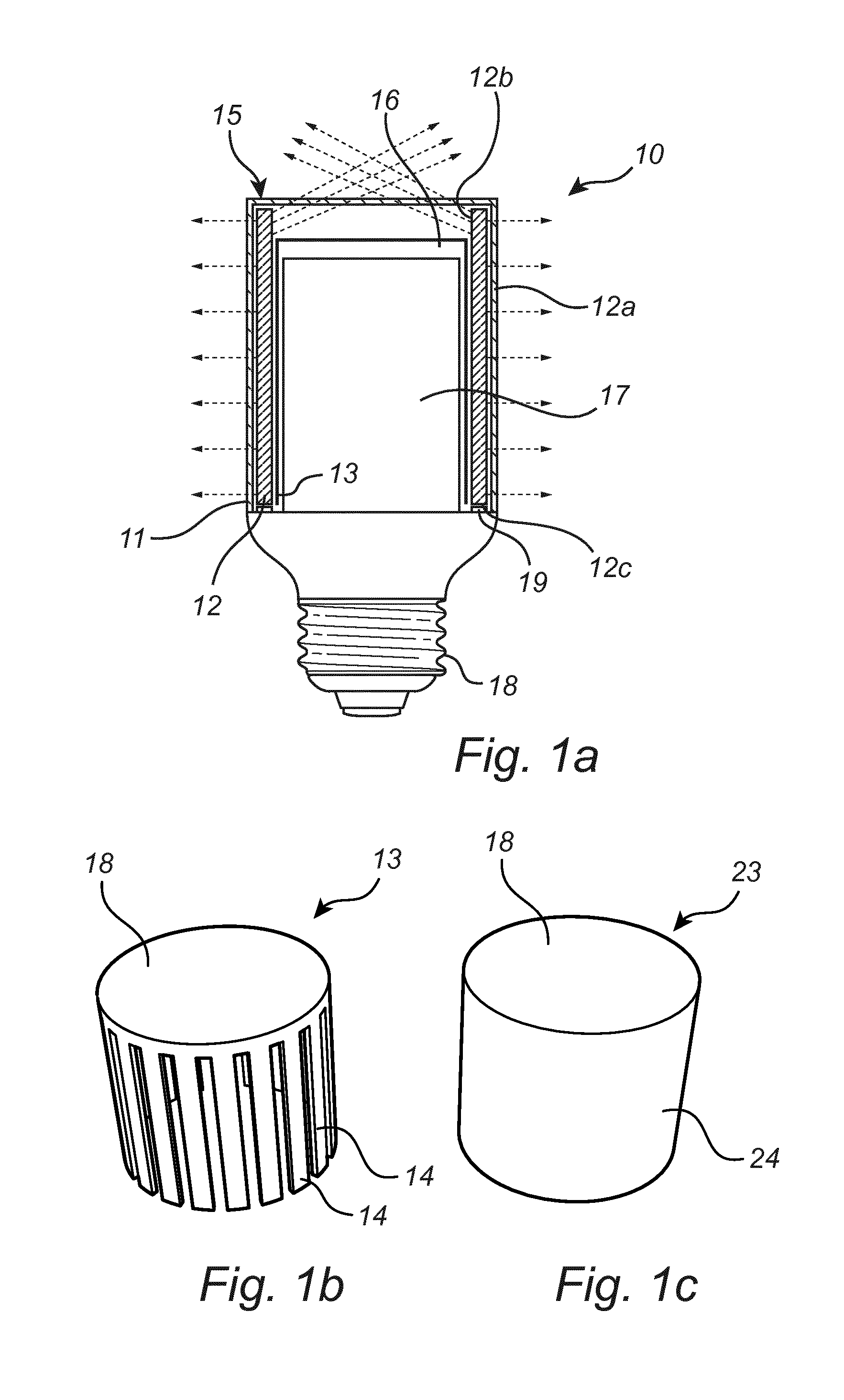
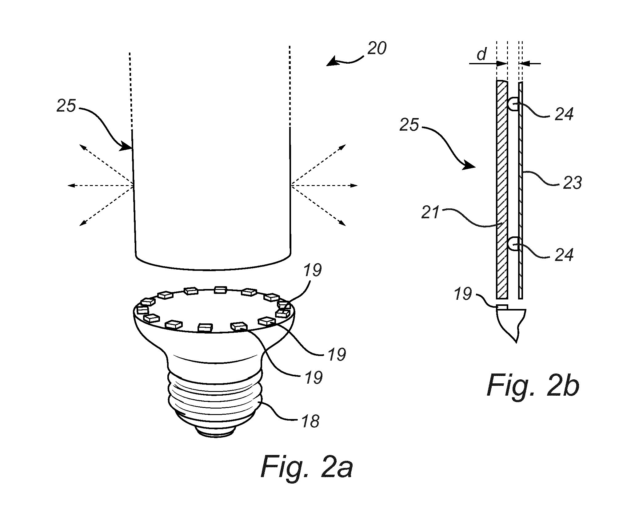
[0021]FIG. 1a is a schematic partly cut open cross sectional side view of an embodiment of a lighting device 10, here a retro fit light bulb, comprising an envelope 15 which encloses / or surrounds an internal volume 16. The envelope 15 is engaged with a base 18, which here is implemented with an Edison base for use with a conventional light bulb socket. The base 18 is configured to connect a power supply to driving circuitry 17 arranged to drive the light source 19 of the lighting device 10. The envelope 15 comprises a transparent encapsulation layer 11, e.g. from glass, and a light guide 12, here a solid hollow cylinder shaped body with a...


PUM


Abstract

There is provided a lighting device (10) which is suitable for a retrofit LED lamp, and which comprises an envelope (15) surrounding an inner volume (16), of which envelope an outer surface (12a) is arranged for distributing light from a multiple of light sources (19) of the lighting device. An inner surface (12b) of the envelope is utilized for providing a low thermal resistance of the lighting device on a system level by being at least partly covered by a sheet metal element (13). Driver electronics (17) of the light sources are arranged within the inner volume.

Description

FIELD OF THE INVENTION[0001]The present invention relates generally to a lighting device, and more particularly to a solid state lighting device comprising a multiple of light sources, an envelope and a heat spreader element arranged at the envelope.BACKGROUND OF THE INVENTION[0002]Lighting devices such as light emitting diode (LED) based light bulbs, or LED lamps, are generally known. A LED lamp concept for a high intensity, high lumen output, is typically limited by its thermal properties and available space for the driver electronics. US 2012 / 0139403 A1 discloses a solid state lighting device comprising LEDs optically coupled to an optical guide, which optical guide encloses an inner volume, and a thermal guide. The thermal guide is integrated within the optical guide for providing thermal conduction from the LEDs and is either co-extensively proximate to an area of the optical guide or is arranged within the inner volume of the optical guide.[0003]The system described above is g...

Claims


Application Information

Patent Timeline
Patent Type & Authority Applications(United States)
IPC IPC(8): F21K99/00F21V29/70F21V29/89F21V3/04F21V29/505
CPCF21K9/135F21K9/1355F21K9/52F21Y2101/02F21V29/70F21V29/89F21V3/04F21V29/505F21V29/506F21K9/23F21K9/232F21K9/61F21Y2115/10F21Y2107/30F21K9/00F21V3/00
Inventor MARINUS, ANTONIUS ADRIANUS MARIALIEDENBAUM, COEN THEODORUS HUBERTUS FRANSISCUSEGGINK, HENDRIK JAN
Owner SIGNIFY HLDG BV
Why Eureka
Try Eureka