
Electrochemical stack device

a stack device and electrochemical technology, applied in the direction of electrochemical generators, fuel cells, cells, etc., can solve the problems of difficult manufacturing and therefore expensive production, difficult to control the sealing between the various reactants and products, and difficult to apply uniform pressure and achieve a regular distance between each cell. , to achieve the effect of simple and economical production and assembly

Active Publication Date: 2016-04-28
SWISS HYDROGEN
View PDF6 Cites 4 Cited by
  • Summary
  • Abstract
  • Description
  • Claims
  • Application Information

AI Technical Summary

Benefits of technology

This patent is about a new electrochemical device that protects its membrane and allows for repeatable pressure and distance between cells. It is easy and economical to produce and assemble, minimizing the risk of losing sealing. Its cells have few elements, making them efficient and reliable.

Problems solved by technology

Consequently, high pressure is applied especially in the peripheral area of the membrane, which may cause it to weaken.
Further, the devices also comprise other support elements, notably supports for the electrodes as described in US 2013 / 0122388, so that known devices comprise a very large number of elements, which are difficult to manufacture and therefore expensive to produce.
Further, the large number of elements makes it difficult to control the sealing between the various reactants and products, while it is evidently desired to avoid mixing hydrogen and oxygen.
US 2013 / 0122388 describes, in particular, the use of a flat sealing gasket arranged at the periphery of the cell, between the frame and a bipolar plate, which makes it difficult to apply uniform pressure and achieve a regular distance between each cell.

Method used


Image

  • Electrochemical stack device
  • Electrochemical stack device
  • Electrochemical stack device

Examples


Embodiment Construction

[0027]In the present description, the term “electrochemical device” includes, in particular, electrolysers and fuel cells, but also applies to devices for implementing other types of electrochemical methods, such as the “chloralkali” process. The present invention may be applied in a similar manner to these devices.

[0028]Such an electrochemical device is intended for the production of products through the electrochemical reaction of reactants, the reactants being hydrogen and oxygen and the products being water in the case of fuel cells, and the reactant being water and the products being hydrogen and oxygen in the case of electrolysers.

[0029]The following description is that of an electrolyser, but may be adapted by those skilled in the art to a fuel cell or to other devices implementing similar electrochemical processes.

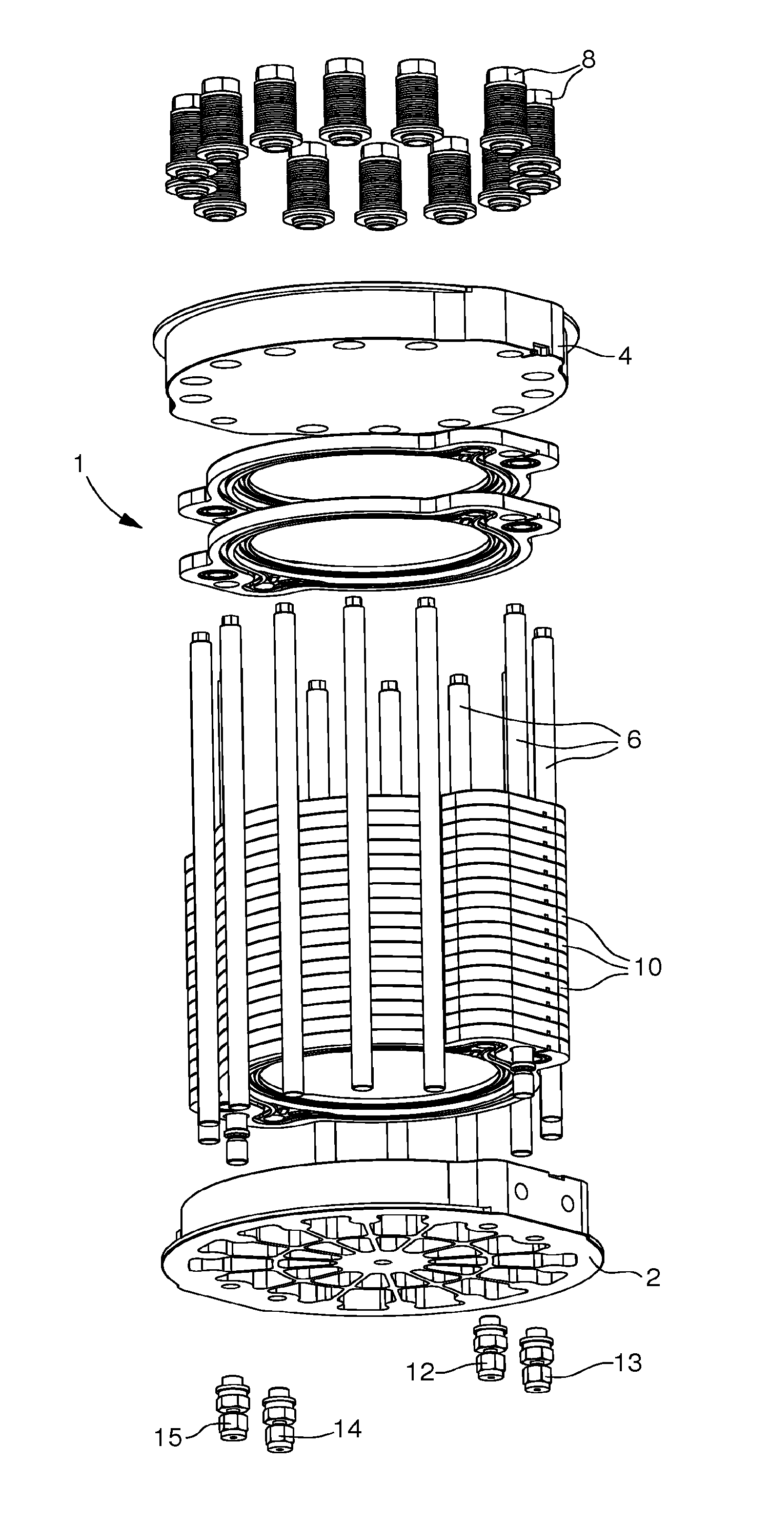
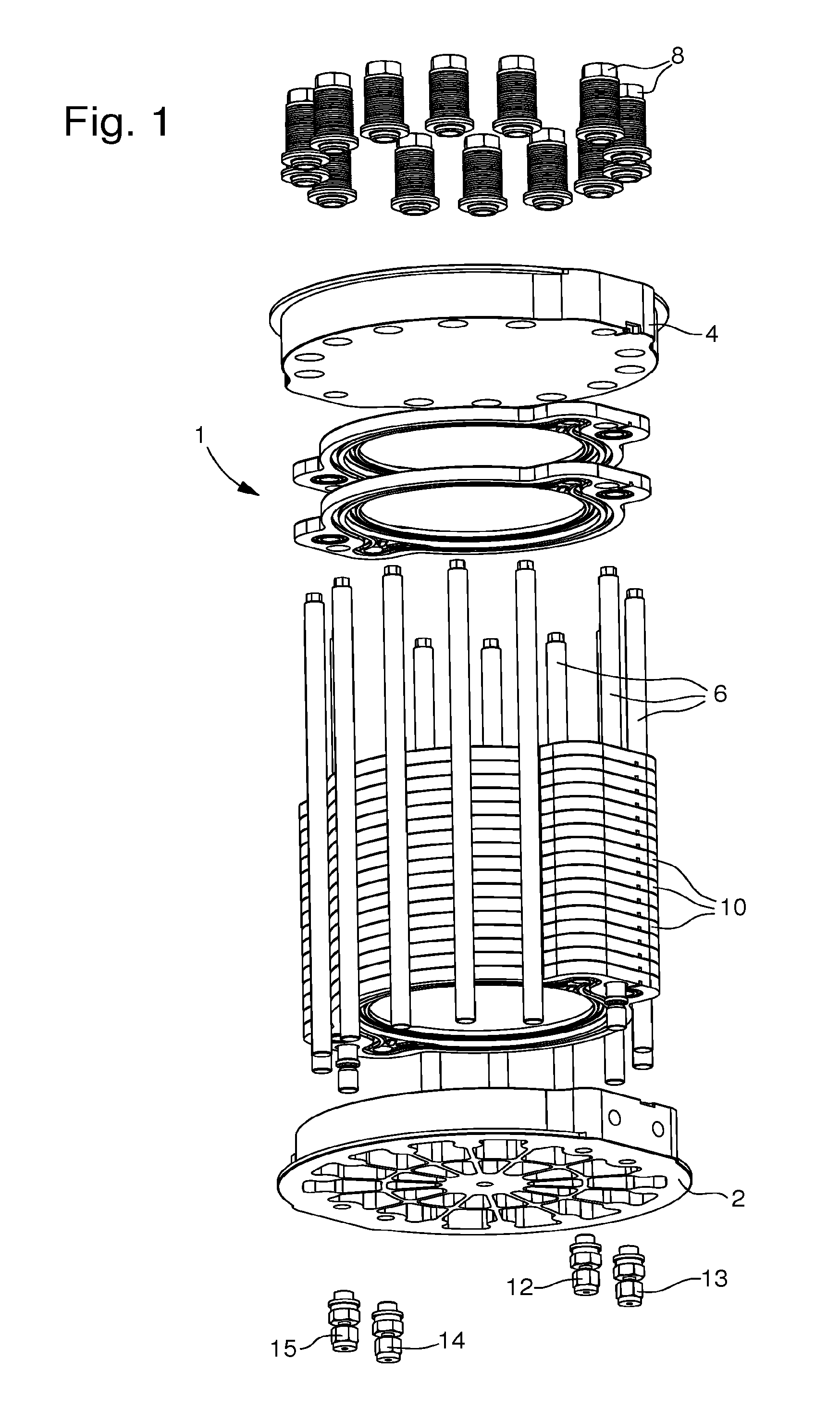
[0030]Referring to FIG. 1, electrochemical device 1 comprises, in a known manner, two end plates 2 and 4 connected by an assembly of axial tie rods 6 respectively ...


PUM

PropertyMeasurementUnit
pressureaaaaaaaaaa
pressureaaaaaaaaaa
heightaaaaaaaaaa

Abstract

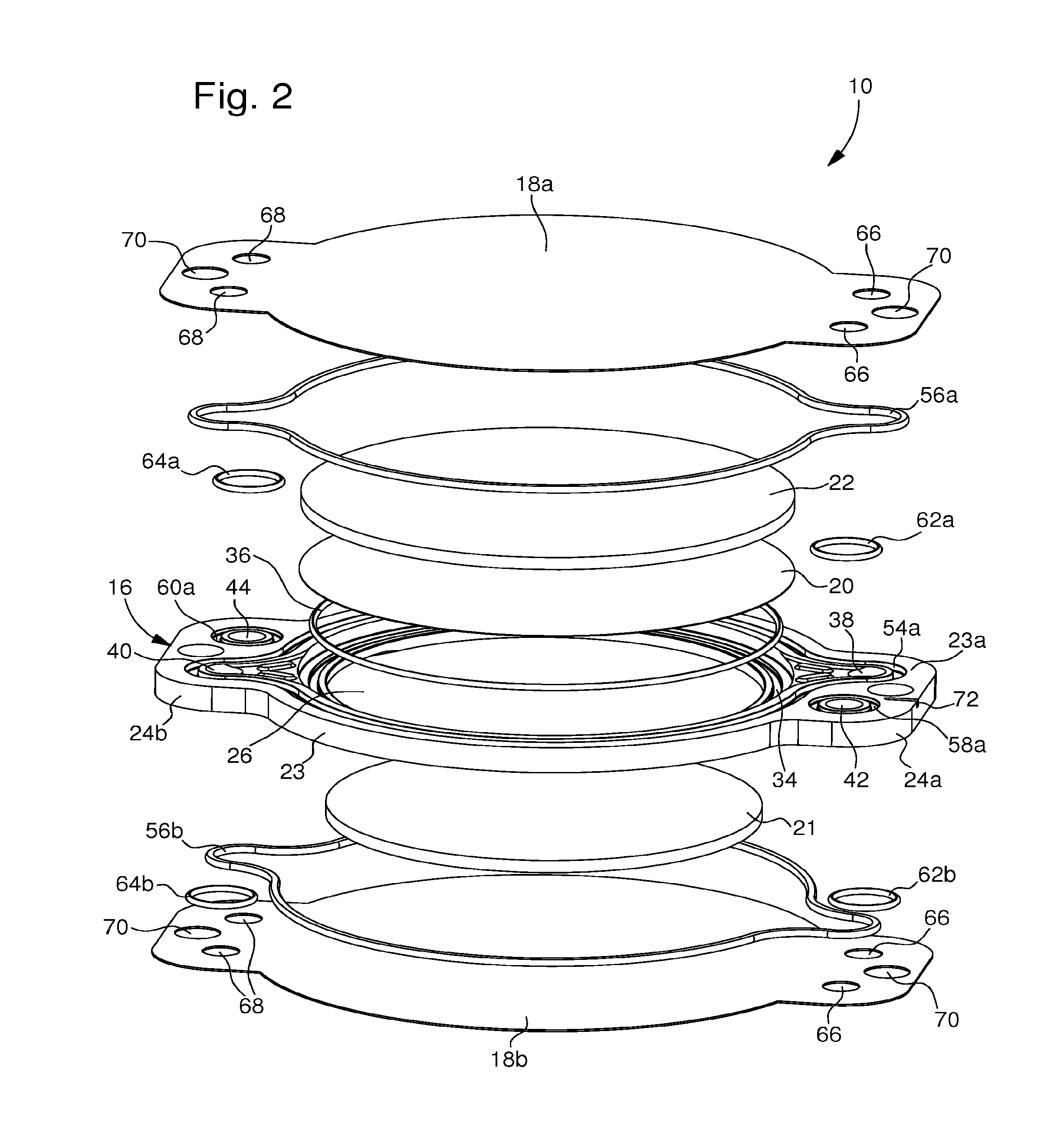
The invention relates to an electrochemical device intended for the production of products through electrochemical reaction of reactants, said electrochemical device comprising a stack of electrochemical cells (10), each cell (10) comprising a structure (16), two bipolar plates (18a, 18b) shared with adjacent cells (10), a membrane / electrode assembly (20) and two intermediate elements (21, 22) arranged to carry a current and the reactants / products to / from the membrane / electrode assembly (20).According to the invention, said structure (16) of the cell (10) comprises a single frame (23) made in one piece, said frame (23) having upper and lower faces respectively arranged to form a plane contact with the bipolar plates (18a, 18b) disposed on either side of said frame (23), and a central opening (26) arranged to receive the membrane / electrode assembly (20) and the two intermediate elements (21, 22), said frame (23) comprising all the orifices (38, 40, 42, 44) necessary for feeding reactants and evacuating products, and housings (34, 54a, 58a, 60a) arranged to receive sealing means (36, 56a, 56b; 62a, 62b, 64a, 64b) ensuring the sealing of each reactant and product.

Description

[0001]This application claims priority from European Patent Application No. 14190301.3 filed on Oct. 24, 2014, the entire disclosure of which is hereby incorporated herein by reference.FIELD OF THE INVENTION[0002]The invention relates to an electrochemical device intended for the production of products through the electrochemical reaction of reactants, said electrochemical device comprising a stack of electrochemical cells, each cell comprising a structure, two bipolar plates shared with adjacent cells, a membrane / electrode assembly and two intermediate elements arranged to carry a current and the reactants / products to / from the membrane / electrode assembly.BACKGROUND OF THE INVENTION[0003]Such devices are known to those skilled in the art and are generally used as electrolyser to produce oxygen and hydrogen from water and electricity or as a fuel cell to produce water and electricity from oxygen and hydrogen. Among such devices, ion exchange membrane devices of the AEM (alkaline exch...

Claims


Application Information

Patent Timeline
Patent Type & Authority Applications(United States)
IPC IPC(8): C25B9/20C25B15/08
CPCC25B15/08C25B9/206C25B9/77H01M8/0273H01M8/0297H01M8/2465Y02E60/50Y02P70/50Y02E60/36
Inventor GASHI, REXHEPSHAPIRO, DANIELVARKARAKI, ELLI
Owner SWISS HYDROGEN
Learn More