
Corn Header Including Kernel Sensor for a Combine Harvester

a corn harvester and corn head technology, applied in the field of combine harvesters, can solve the problems of corn ears getting stuck more easily between the deck plates, corn ears may form obstructions or trash buildup, and substantial amount of kernels will become detached

Active Publication Date: 2016-04-28
BLUE LEAF I P INC
View PDF0 Cites 12 Cited by
  • Summary
  • Abstract
  • Description
  • Claims
  • Application Information

AI Technical Summary

Benefits of technology

The patent describes a problem with harvesting corn where the kernels become detached from the corn ears and scattered around, causing noise and damage to the machine. The patent proposes using a microphone to sense the noise and a filter to eliminate other noise sources. A control unit then adjusts the stalk receiving channel to reduce the impact of the kernels on the machine. Overall, the invention improves the efficiency of the harvesting process and reduces damage to the machine.

Problems solved by technology

But, a disadvantage is that corn ears may get stuck more easily between the deck plates.
As a result, these ears may form an obstruction or trash build up for a next stalk entering the harvesting unit.
Further, when such a corn ear remains stuck, a substantial amount of kernels will become detached until the ear is reduced in size and falls through the gap.
As such, when the gap is set too large, considerable losses may occur.
In the second instance, if the pinch force is too great, stalks may get caught between the deck plates and bunch up in the channel and be damaged or broken such that, again, ears are lost, and more trash may be retained and carried by the gathering chains into the header.
However, if the operator lacks experience, or is inattentive, the channel width can be too big or small, resulting in the above listed problems.
As another problem, sugars from the stalks and dust adhered thereby to the plates and surrounding structure so as to reduce and even overcome the spring forces and inhibit free lateral adjusting movements of the plates, such that they can stick open too widely or too narrowly so as to undesirably affect the pinching force, disrupt stalk flow and ear removal, and the like.

Method used


Image

  • Corn Header Including Kernel Sensor for a Combine Harvester
  • Corn Header Including Kernel Sensor for a Combine Harvester
  • Corn Header Including Kernel Sensor for a Combine Harvester

Examples


Embodiment Construction

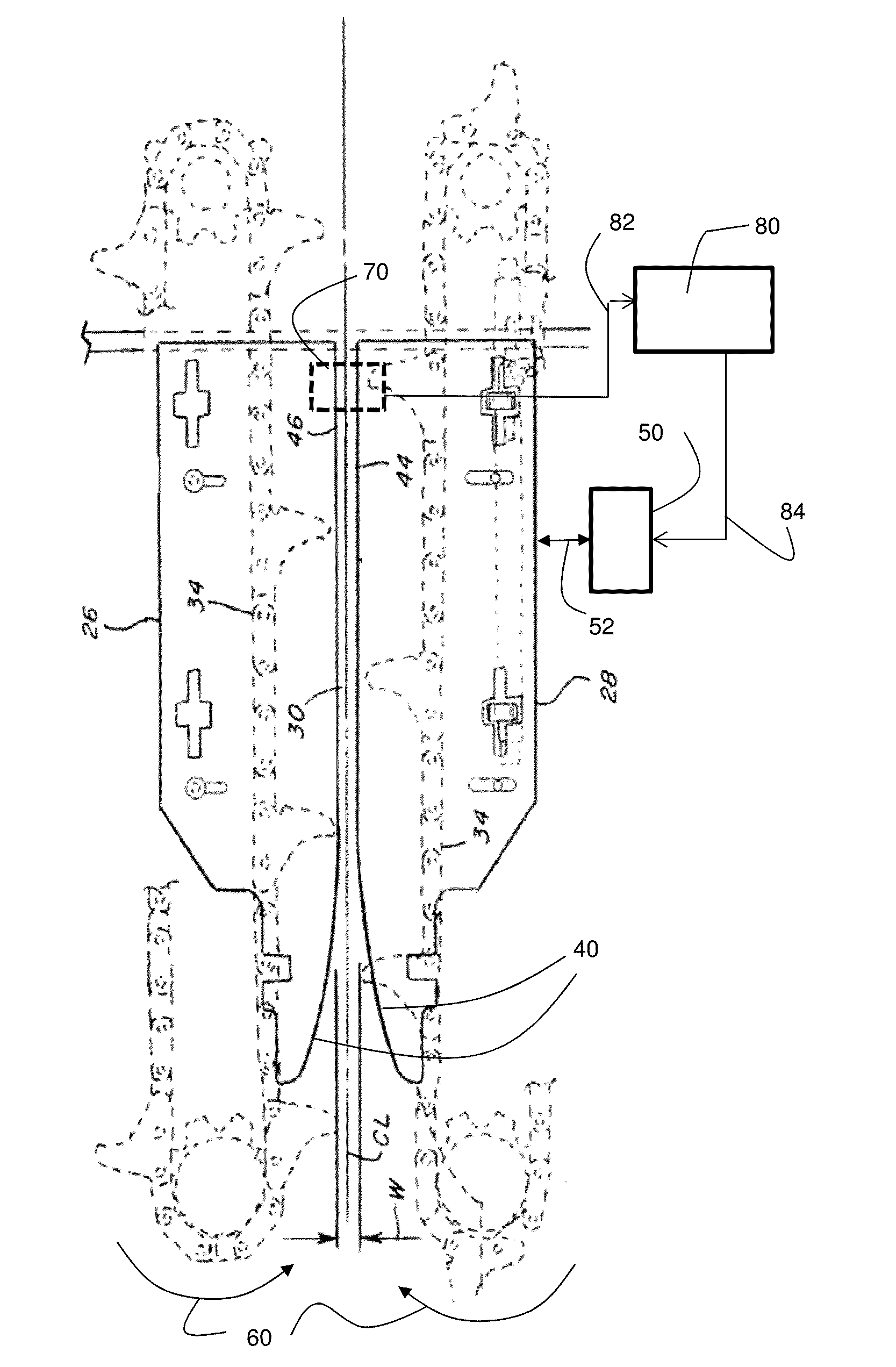
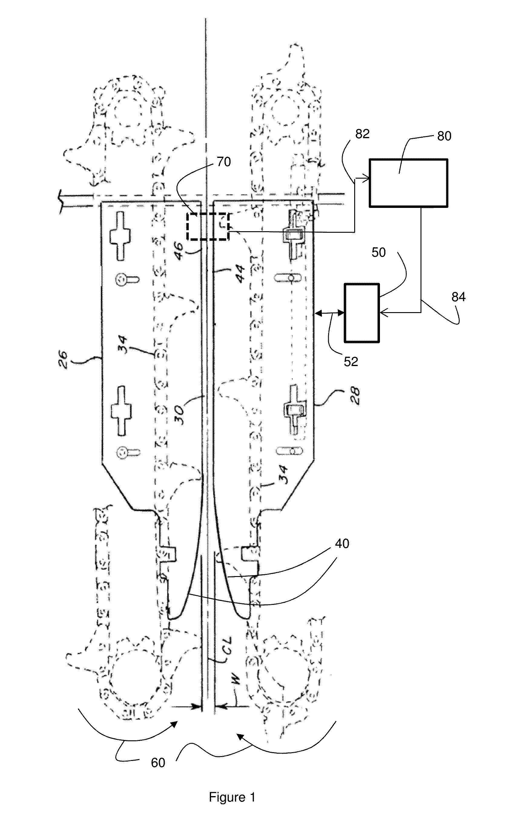
[0030]FIG. 1 schematically shows an harvesting unit 10 as can be applied in a corn header according the present invention. The harvesting unit 10 comprises a deck plate assembly comprising a pair of deck plates 26, 28 that are spaced apart to define a stalk receiving channel 30 that is bound by edges 44, 46 of the deck plates 26, 28 and has a width W. During operation, a row of stalks is received along the centreline CL via the curved edges 40 of the deck plates 26, 28.

[0031]FIG. 1 further shows an actuator assembly comprising an actuator 50, the actuator being configured to exert a force on the deck plate 28 (indicated by the arrow 52), in order to adjust a position of the deck plate, thereby adjusting the width W of the stalk receiving channel 30. As an alternative to using only a single actuator 50 to adjust the width W of the stalk receiving channel 30, a plurality of actuator may be applied as well, acting on one of the deck plates or on both deck plates. FIG. 1 further partly ...


PUM


Abstract

A corn header includes a plurality of harvesting units to separate corn ears from corn stalks. Each harvesting unit has a deck plate assembly, and an actuator assembly to adjust a width of a stalk receiving channel by adjusting a position of at least a deck plate of the deck plate assembly. A kernel sensor can generate a signal representative of the presence of kernels detached from the ears during the separation of the corn ears from the corn stalks by the harvesting units and a control unit to receive the signal from the kernel sensor and generate an actuator control signal for controlling the actuator assemblies of the plurality of harvesting units, thereby controlling the width of the stalk receiving channels of the harvesting units.

Description

[0001]This application claims priority to Belgium Application BE2014 / 0794 filed Oct. 27, 2014, which is incorporated herein by reference in its entirety.FIELD OF THE INVENTION[0002]The invention relates to the field of combine harvesters for harvesting corn, and more specifically to controlling a harvesting unit of a corn header of such a harvester.BACKGROUND OF THE INVENTION[0003]Corn plants are typically planted in rows spaced a predetermined distance apart. Harvesting units of corn headers are spaced a corresponding distance apart so as to be capable of following the rows while inducting the corn plants. When entering and moving through a stand of corn, the harvesting units of the header are typically preceded by row dividers that separate the adjacent rows of plants for harvesting by the respective harvesting units. The harvesting units are configured and operable for receiving the stalks of the corn plants of the respective rows in succession, and removing the full or intact ea...

Claims


Application Information

Patent Timeline
Patent Type & Authority Applications(United States)
IPC IPC(8): A01D41/127A01D45/02
CPCA01D41/127A01D45/025A01D45/023A01D45/021A01D41/1235A01D41/1273
Inventor JONGMANS, DREMISSOTTEN, BART M.A.TALLIR, FREDERIKVANDAMME, WILLEMVIAENE, KAREL M.C.
Owner BLUE LEAF I P INC
Learn More