
Sensor System With Active Illumination

a technology of active illumination and sensor system, which is applied in the direction of optical radiation measurement, distance measurement, instruments, etc., can solve the problems of consuming the dynamic range of the system, system needs to acquire two separate images, etc., and achieves highly robust eye tracking and minimized interferences between different acquisition systems

Active Publication Date: 2016-04-21
AMS SENSORS SINGAPORE PTE LTD
View PDF1 Cites 36 Cited by
  • Summary
  • Abstract
  • Description
  • Claims
  • Application Information

AI Technical Summary

Benefits of technology

The patent aims to improve the dynamic range of an imaging system, increase resolution for three-dimensional measurement, and reduce optical power consumption. It also provides a two-dimensional intensity and a three-dimensional imaging system. The invention proposes a timing adaptation for an imaging system with a time-of-flight sensor and an illumination source to capture fewer samples per frame for time of flight measurements.

Problems solved by technology

The drawback of such an approach is first that the system needs to acquire two separate images.
Even though the background light signal is not required, it eats up the dynamic range of the system.

Method used


Image

  • Sensor System With Active Illumination
  • Sensor System With Active Illumination
  • Sensor System With Active Illumination

Examples


Embodiment Construction

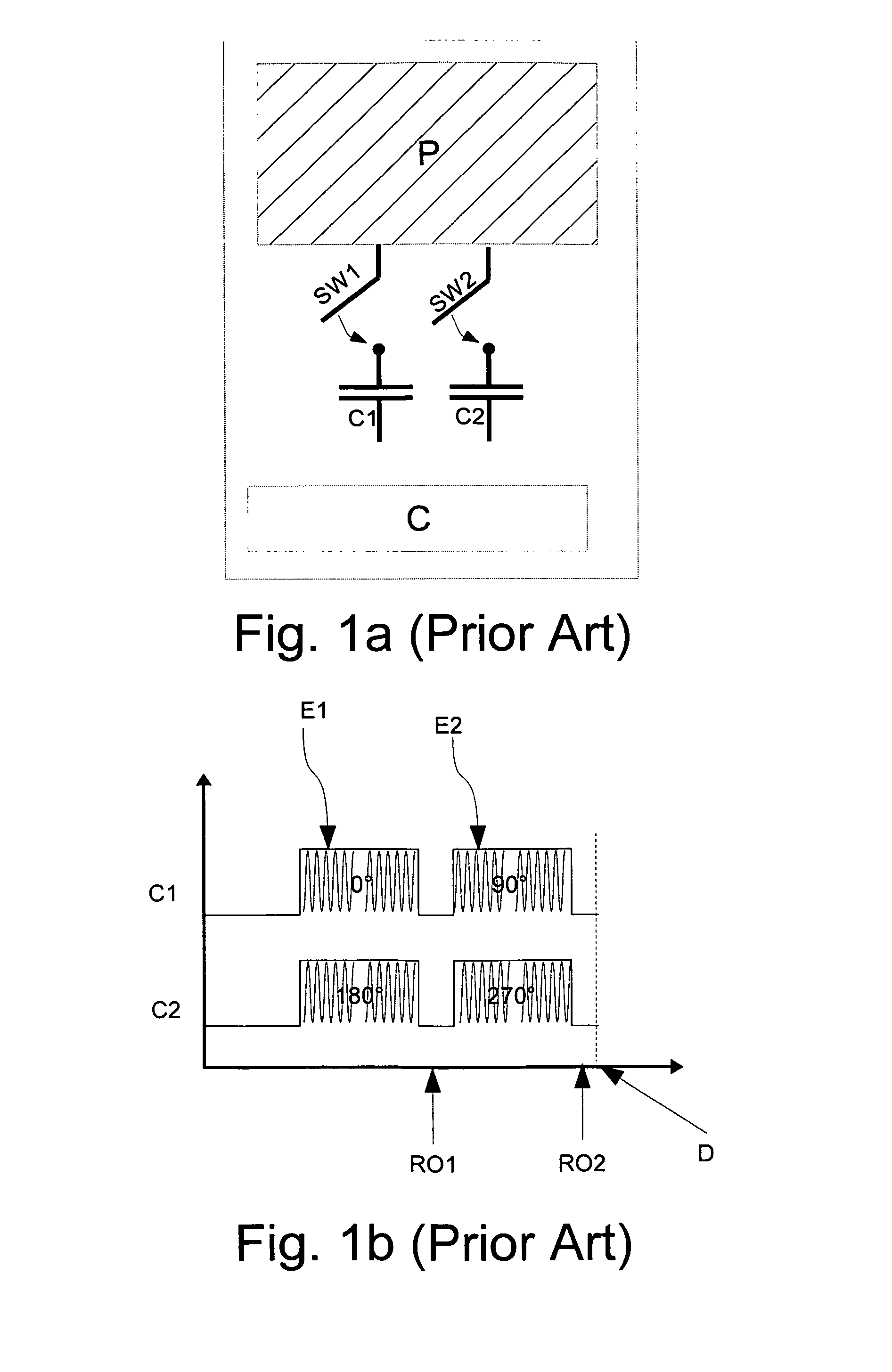
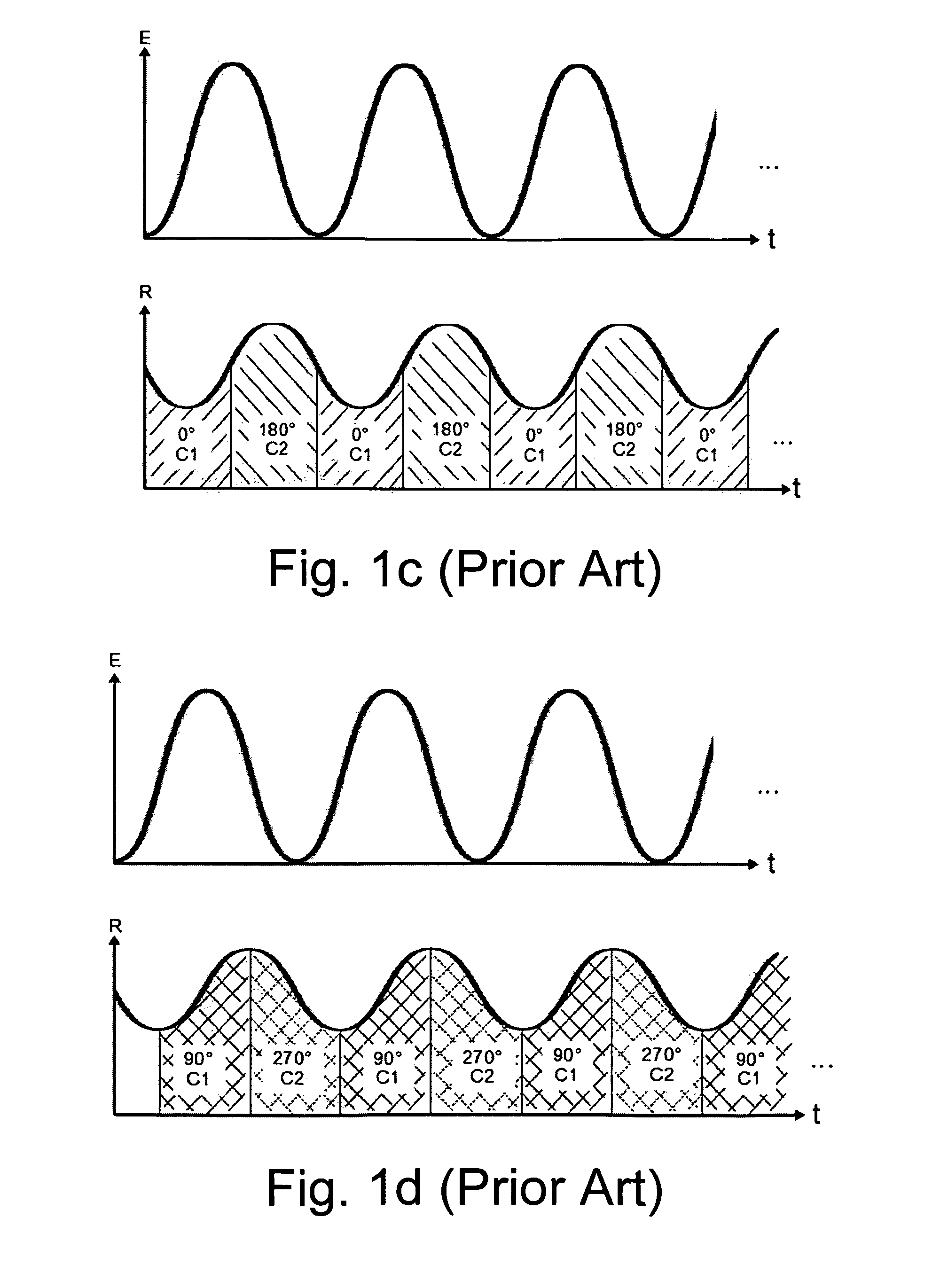
[0050]Time-of-flight imaging systems area capable to determine the time it takes to the emitted light to travel from the measurement system to the object and back. The emitted light signal is reflected by an object at a certain distance. This distance corresponds to a time delay from the emitted signal to the received signal caused by the travel time of the light from the measurement system to the object and back. In indirect time-of-flight measurements, the distance-dependant time delay corresponds to a phase delay of the emitted to the received signals. Further, the received signal not only includes the back-reflected emitted signal, but may also have background light signal from e.g. the sun or other light sources. A state-of-the-art time-of-flight pixel is illustrated in FIG. 1a. The time-of-flight pixel includes a photo-sensitive area P, connected with a first switch SW1 to storage node C1 and connected with a second switch SW2 to storage node C2. The sampling of the photo-gene...


PUM


Abstract

The present invention relates to vision sensors based on an active illumination. An imaging system includes an imaging sensor and is adapted to process an image of a scene being illuminated by at least two different illumination sources each having a wavelength in the near infrared range. In a variant, the imaging system is adapted to use an illumination source having a modulation frequency below the modulation frequency used to perform a three dimensional time of flight measurement. In a variant, the imaging system is adapted to acquire a reduced number of samples per frame than used in time of flight measurements.

Description

FIELD OF THE INVENTION[0001]The present invention relates to vision sensors based on an active illumination. The invention improves image quality of an active imaging system, improves the dynamic range and its background light stability. Such sensors typically are used to detect and measure their surroundings, objects or people.BACKGROUND ART[0002]Active illuminations are implemented in many camera designs to improve the camera measurement results. Camera is understood as an electro-optical device containing an image sensor with an array of pixels.[0003]In many machine vision applications, active illuminations are used to guarantee for certain light intensity level on the camera system. By doing so. the performance of an active system becomes less prone to lighting changes in its surrounding. The stability and reliability is improved. In addition, by adding illumination power to the system, shorter exposures can be set and higher frame rates achieved.[0004]Other sensors with an acti...

Claims


Application Information

Patent Timeline
IPC IPC(8): G01S17/89G01S7/491G01S7/4911G01S7/4915G01S17/894
CPCG01S7/4915G01S17/89G01S7/484G01S7/4911G01S17/894
Inventor OGGIER, THIERRYDESCHLER, MATHIASKALOUSTIAN, STEPHANE
Owner AMS SENSORS SINGAPORE PTE LTD
Learn More