
Molding system and method for directly gas-cooling a molding object

a molding object and gas-cooling technology, which is applied in the direction of auxillary shaping apparatus, manufacturing tools, ceramic shaping apparatus, etc., can solve the problems of affecting production efficiency, poor cooling efficiency, and shortening the molding cycle of finished products, so as to achieve the effect of shortening the molding cycle of the molding obj

Active Publication Date: 2016-04-21
QUANTA COMPUTER INC
View PDF1 Cites 12 Cited by
  • Summary
  • Abstract
  • Description
  • Claims
  • Application Information

AI Technical Summary

Benefits of technology

The present invention provides a molding system and method for directly gas-cooling a molding object to resolve inconveniences and shortcomings of the prior art. The technical effects include shortening the entire molding cycle of the molding object, saving energy and maintenance costs for production equipment, and rapidly heating / cooling the surfaces of the mold cores during the molding process.

Problems solved by technology

However, utilizing cooling water as a cooling medium to cool the forming mold has the following disadvantages.
In addition, since the heat energy in the mold core needs to be carried away indirectly through such equipment and the water channels buried in the mold core, not only is the cooling efficiency poor to lengthen the cooling time, but the entire molding cycle of the finished product is also lengthened, thus affecting production efficiency.
In addition, when cooling water flows circularly in the forming mold for a long time, the cooling water may generate scales having a specific thickness on inner walls of the circulation water channels.
The scales isolate the cooling water from the inner walls of the circulation water channels that leads to decline in cooling performance.
In additional to that, when the cooling water at a low temperature flows circularly in the forming mold, condensed water droplets will be generated on the inner surface of the cavity of the forming mold due to the low-temperature cooling water, thus affecting the molding quality of the finished product.

Method used


Image

  • Molding system and method for directly gas-cooling a molding object
  • Molding system and method for directly gas-cooling a molding object
  • Molding system and method for directly gas-cooling a molding object

Examples


Embodiment Construction

[0030]In the following detailed description, for purposes of explanation, numerous specific details are set forth in order to provide a thorough understanding of the disclosed embodiments. It will be apparent, however, that one or more embodiments may be practiced without these specific details. In other instances, well-known structures and devices are schematically depicted in order to simplify the drawings.

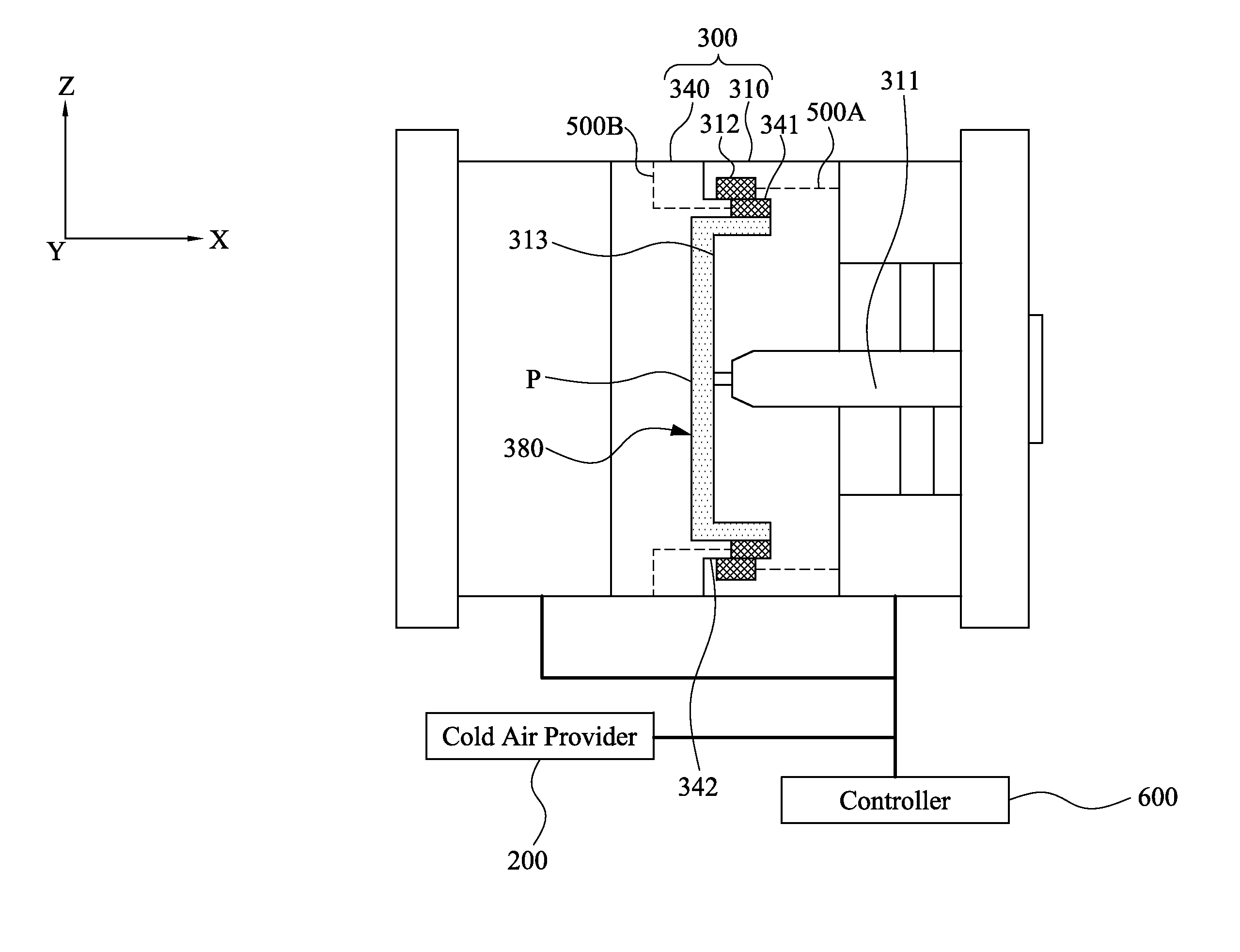
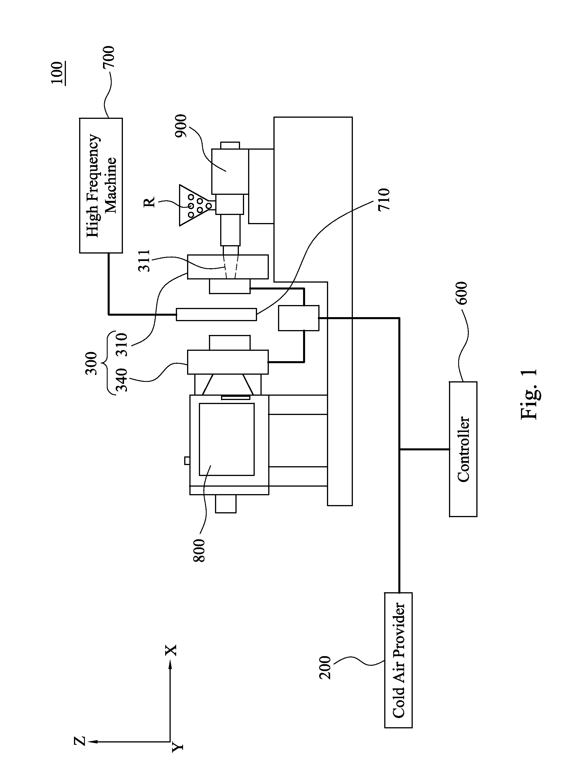
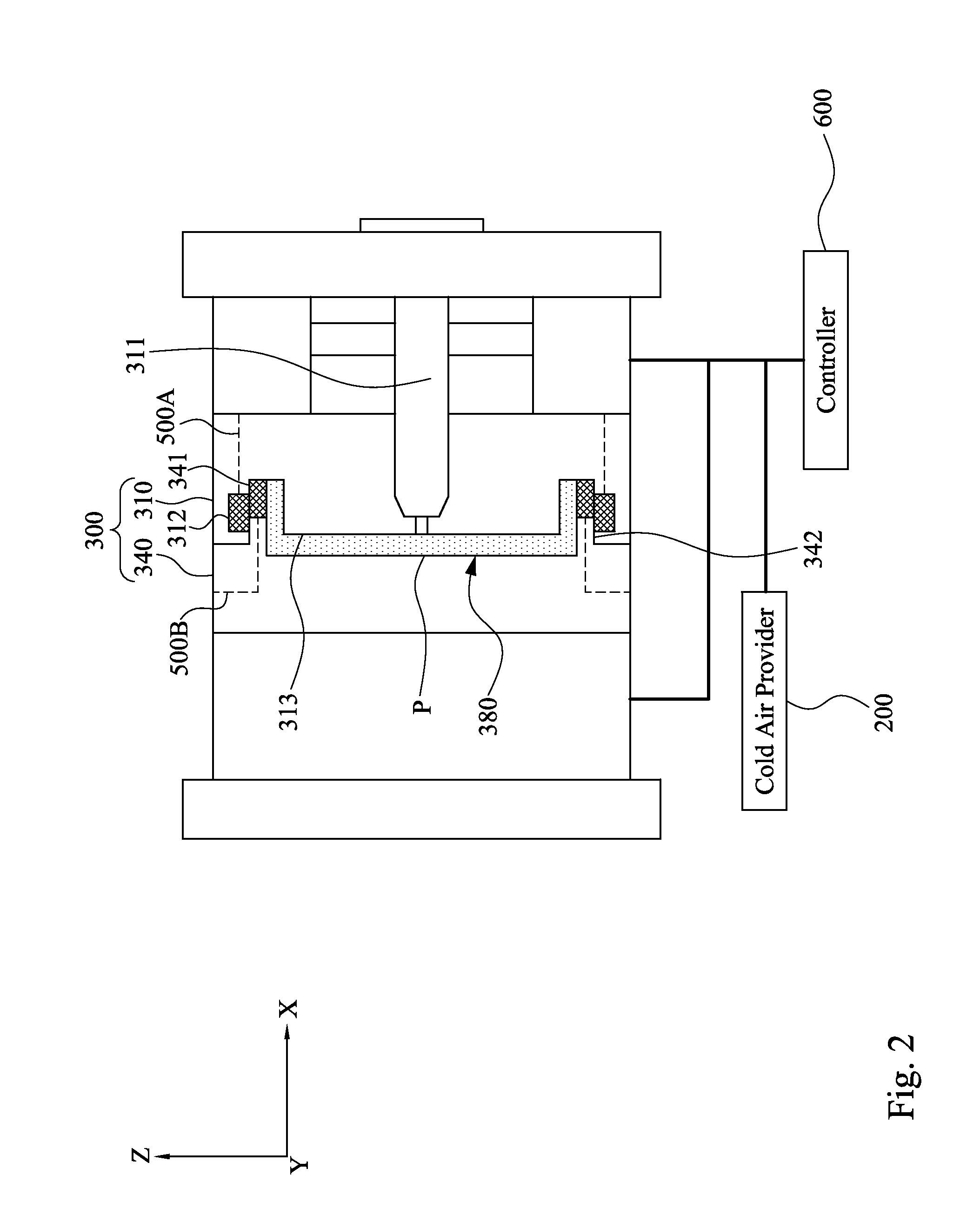
[0031]FIG. 1 depicts a schematic diagram of a molding system 100 for directly gas-cooling a molding object according to one embodiment of this invention. The molding system 100 comprises a cold air provider 200, a forming mold 300, a controller 600, a high frequency machine 700, a transmission device 800 of an injection molding machine, and a plastic injection unit 900 of the injection molding machine. The cold air provider 200 is connected to the controller 600 and the forming mold 300. The forming mold 300 is connected to the transmission device 800 and the plastic injection u...


PUM

PropertyMeasurementUnit
Timeaaaaaaaaaa
Temperatureaaaaaaaaaa

Abstract

A molding system for directly gas-cooling a molding object includes a cold air provider, two molding parts, a plurality of outlets, at least one air-providing molding part, at least one air passage, and a controller. The two molding parts are closed detachably to co-define a forming cavity therebetween. The outlets are arranged on the air-providing molding part. The air passage is connected to the cold air provider and the outlets. The controller drives the cold air provider to provide cold air to a molding object in the forming cavity directly when the two molding parts are separating.

Description

RELATED APPLICATIONS[0001]This application claims priority to Taiwan Application Serial Number 103135997, filed Oct. 17, 2014, which is herein incorporated by reference.BACKGROUND[0002]1. Field of Invention[0003]The present invention relates to a molding system and method. More particularly, the present invention relates to a molding system and method for directly gas-cooling a molding object.[0004]2. Description of Related Art[0005]The traditional plastic injection molding process comprises the following steps: at first, the plastic material is fed into the feeding tube of the injection molding machine to plasticize the plastic material into molten resin and then the following steps in sequence. The forming mold is closed, the molten resin is injected into the cavity of the forming mold, pressure is held by the injection molding machine, the forming mold is cooled circularly, the forming mold is opened, the finished product is knocked out, and then the finished product is output. A...

Claims


Application Information

Patent Timeline
IPC IPC(8): B29C45/73
CPCB29C45/73B29C45/7312B29C45/7306B29C33/02B29C33/046B29C45/7337B29C2045/7368B29C2045/7387B29C2045/7393
Inventor LIN, SHU-CHEN
Owner QUANTA COMPUTER INC
Learn More