Optical Wiring Systems and Methods
- Summary
- Abstract
- Description
- Claims
- Application Information
AI Technical Summary
Benefits of technology
Problems solved by technology
Method used
Image
Examples
Embodiment Construction
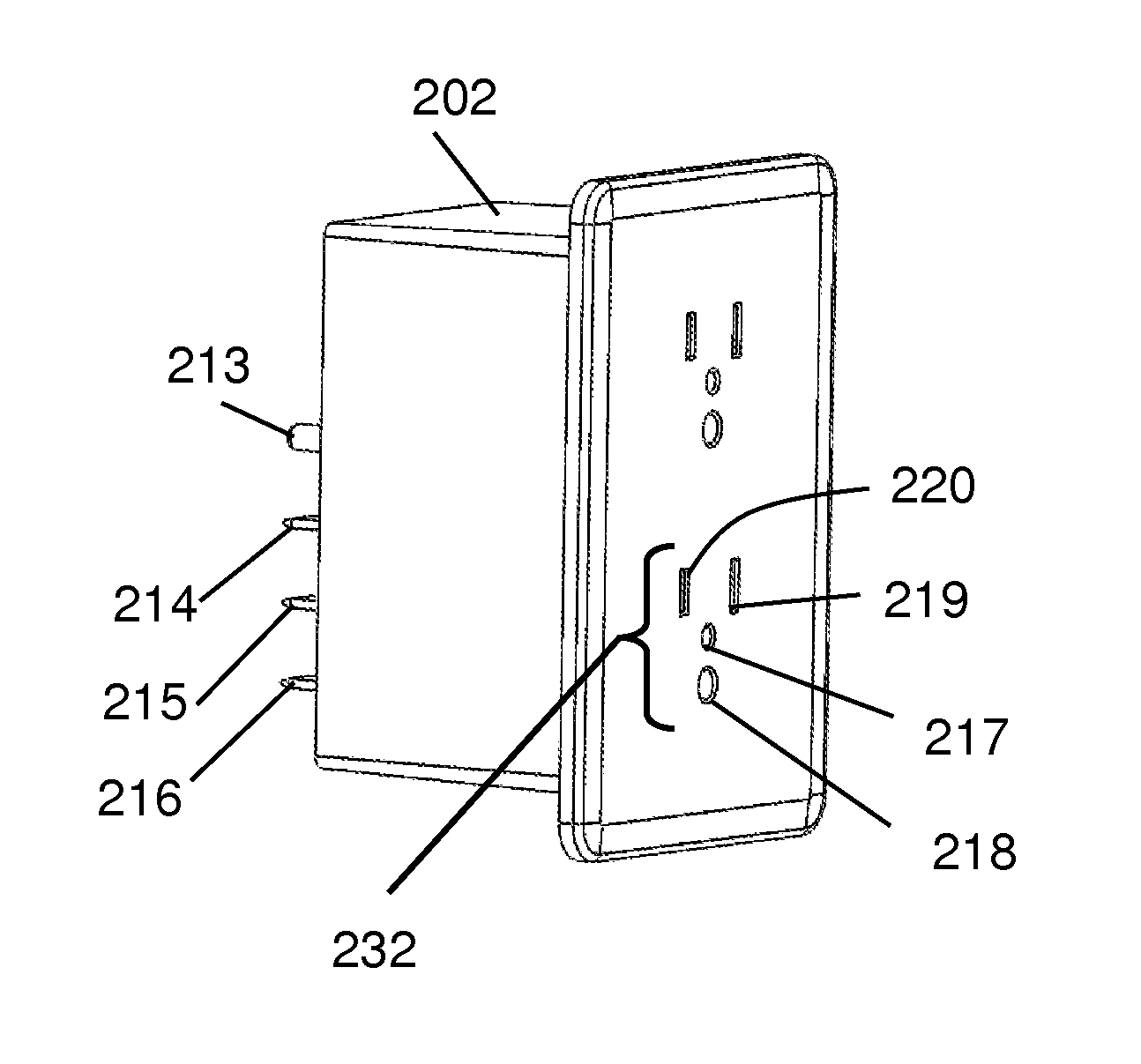
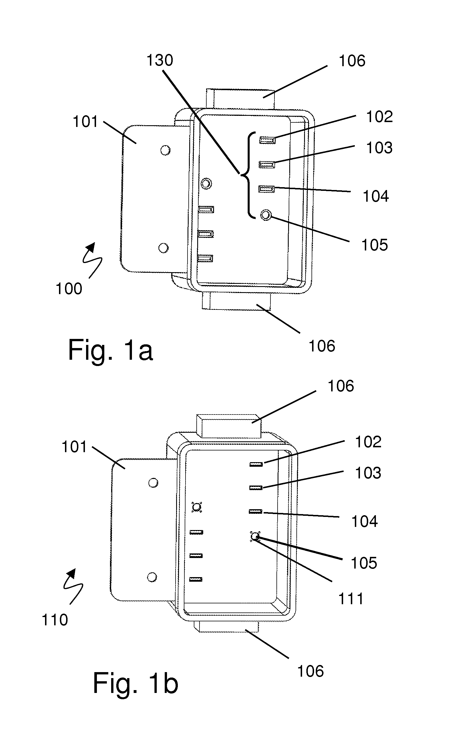
[0118]FIG. 1a illustrates an exemplary termination box for terminating house wiring and interfacing with smart outlets and other devices. FIG. 1a is an isometric view of a termination box 100 showing the basic box 101 with the three wire plus light connections comprising the electrical connectors 102, 103, and 104, and the fiber optic connection 105. The termination box also includes input wiring junctions 106 to connect to building power and optical network. Referring to FIG. 1a, the termination box 100 is part of the backbone of the system. The termination box 100 would be installed similarly to a typical junction box except that all wires and fiber optics are permanently affixed for what is expected to be a very long time. The termination box 100 typically has no active components inside and forms a connection platform for the smart device ports that are plugged into it, which are shown in various Figures in different variations. The power and data are passed from one end 106 to ...
PUM
 Abstract
Description
Claims
Application Information
 - R&D
- Intellectual Property
- Life Sciences
- Materials
- Tech Scout
- Unparalleled Data Quality
- Higher Quality Content
- 60% Fewer Hallucinations
Browse by: Latest US Patents, China's latest patents, Technical Efficacy Thesaurus, Application Domain, Technology Topic, Popular Technical Reports.
© 2025 PatSnap. All rights reserved.Legal|Privacy policy|Modern Slavery Act Transparency Statement|Sitemap|About US| Contact US: help@patsnap.com


