
Assembly for vibrating a compacting drum of a compacting machine

a compacting machine and compacting drum technology, which is applied in the direction of controlling members, soil preservation, controlled members, etc., can solve the problems of reducing fuel consumption, high fuel consumption of the compacting machine, and relative high power demand of the driving motor, so as to reduce the moment of inertia and reduce the effect of inertia

Active Publication Date: 2016-04-14
VOLVO CONSTR EQUIP
View PDF9 Cites 10 Cited by
  • Summary
  • Abstract
  • Description
  • Claims
  • Application Information

AI Technical Summary

Benefits of technology

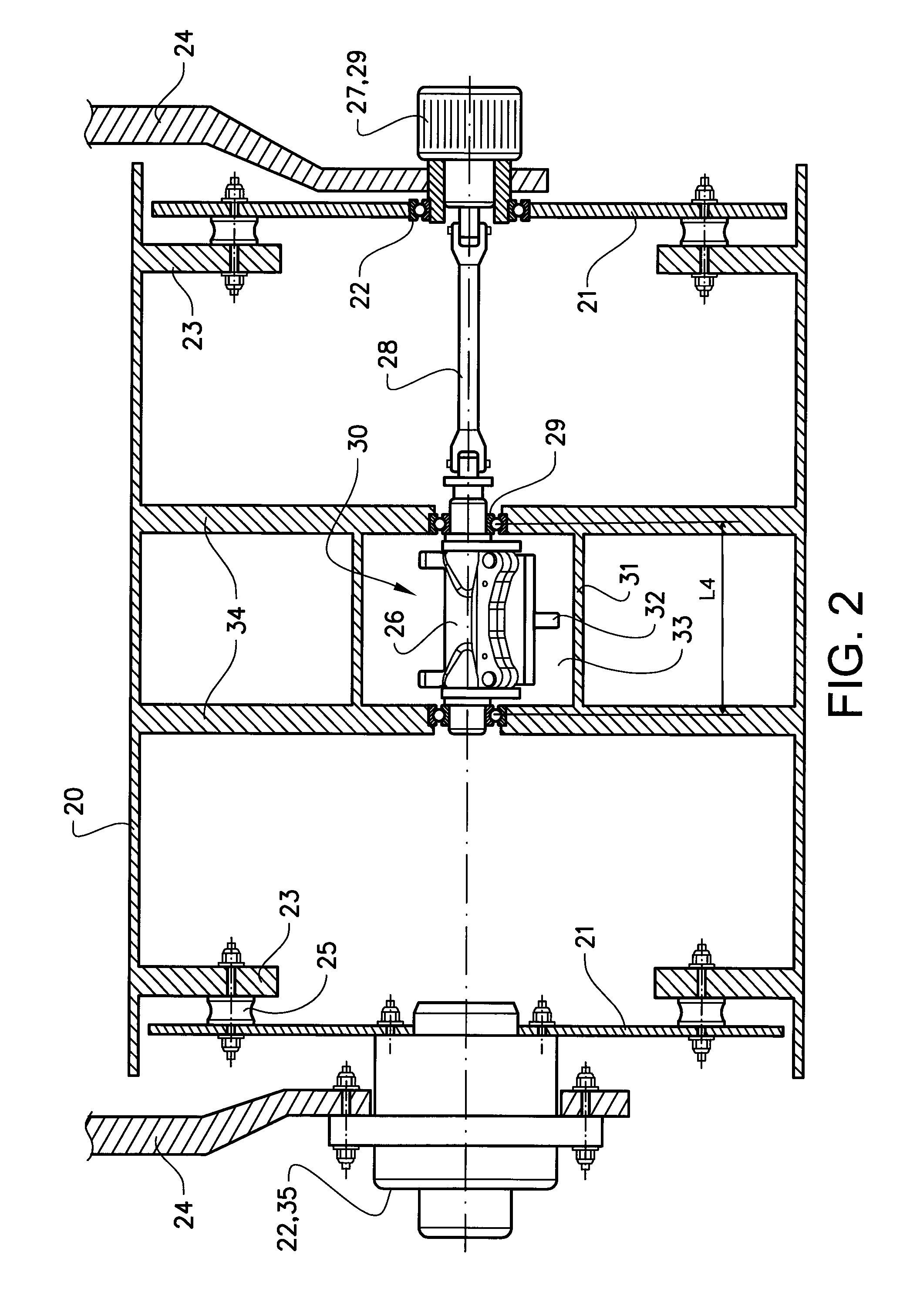
This patent describes a device that reduces the moment of inertia of a rotating shaft. This is achieved by distributing the mass of the outer eccentric member in the axial direction, which reduces the distance between the geometrical rotation axis of the outer eccentric member and the centre of weight of the outer eccentric member in a plane perpendicular to the axial direction. This reduces the moment of inertia, which is the product of the mass and the distance squared. By doing so, the device becomes more stable and easier to handle. Additionally, the absence of an internal cavity in the shaft further contributes to the reduction of moment of inertia.

Problems solved by technology

A disadvantage of the solution of D1 is a relatively high power demand of the driving motor.
However, strong and robust parts imply a high moment of inertia, which implies a relatively high power output of the motor for rotationally powering the assembly, thereby resulting in high fuel consumption of the compacting machine.
By providing the assembly with spring means for clamping the impact force the parts of the assembly, in particular the shaft and the outer eccentric member may be less strong and robust, such that a reduced moment of inertia results, and thereby also reducing the fuel consumption.

Method used


Image

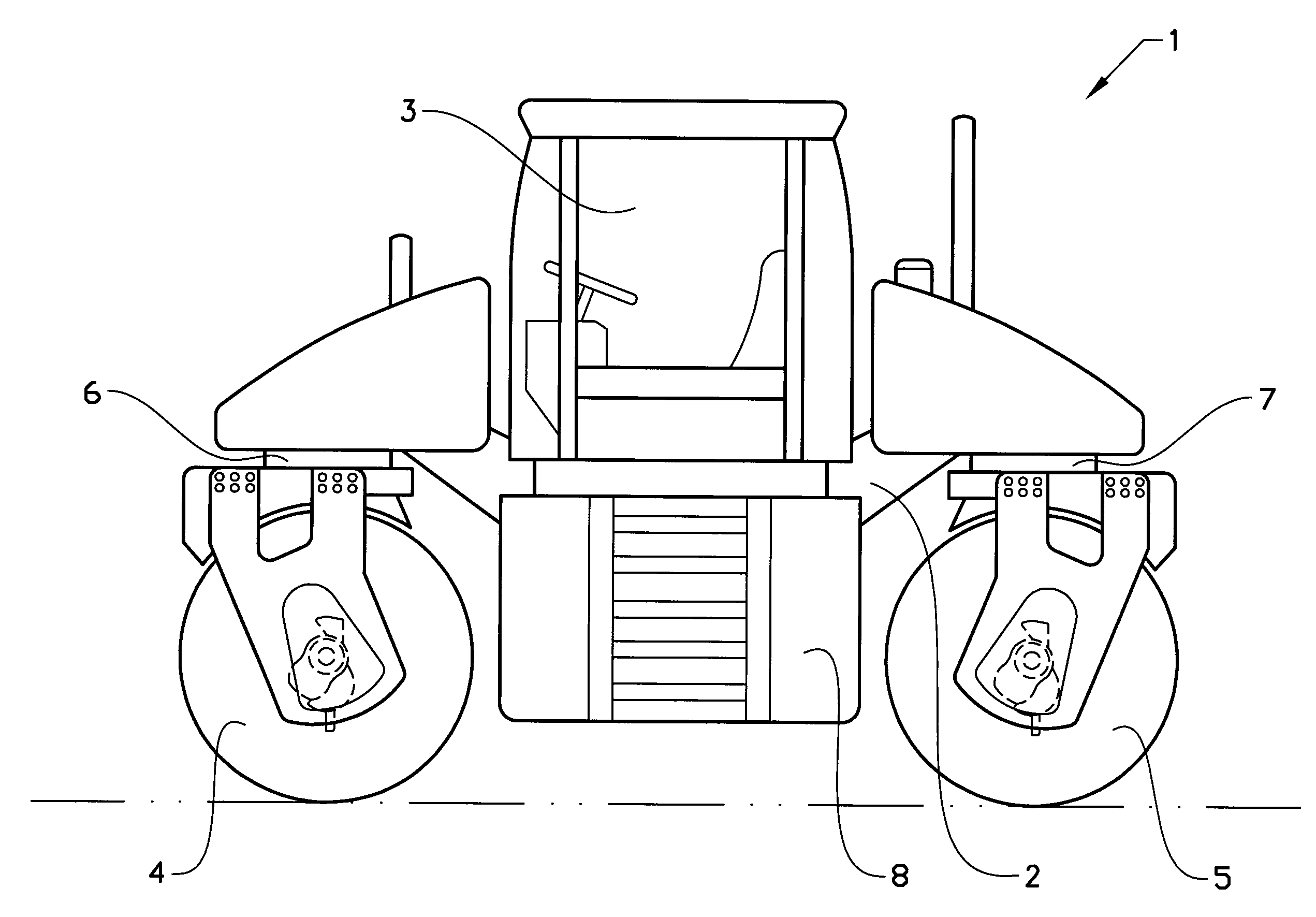
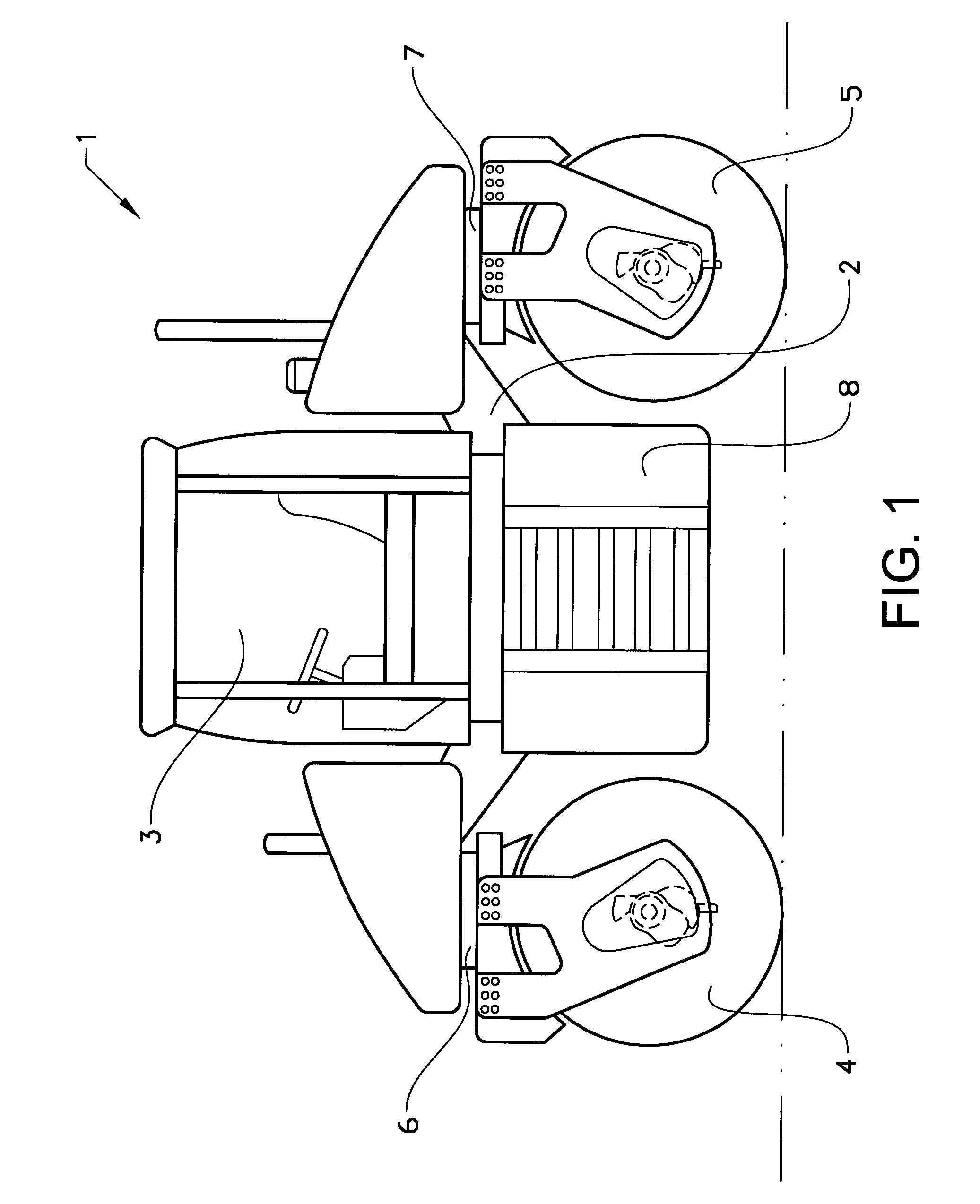
  • Assembly for vibrating a compacting drum of a compacting machine
  • Assembly for vibrating a compacting drum of a compacting machine
  • Assembly for vibrating a compacting drum of a compacting machine

Examples


Embodiment Construction

[0050]Various aspects of the disclosure will hereinafter be described in conjunction with the appended drawings to illustrate and not to limit the disclosure, wherein like designations denote like elements, and variations of the disclosed aspects are not restricted to the specifically shown embodiments, but are applicable on other variations of the disclosure.

[0051]Vibratory steel drums exert forces which increase compactive effort. Vibratory drums have internal eccentric weights that rotate on a shaft. The rotating eccentric weight causes the drum to move in all directions but the effective part is the up and down movement. Vibratory forces are the rapid up and down movements which cause aggregates and soil particles to move. Aggregates in motion tend to re-orient themselves easier so the material compacts easier under the weight of the drum. Vibration is a particularly effective tool for the aggregate or particulate material like sand and gravel. A relatively large compacting mach...


PUM


Abstract

An assembly is provided for vibrating a compacting drum of a compacting machine. The assembly includes a shaft rotatably mountable to a compacting drum of the compacting machine. The centre of mass of the shaft is offset from the geometrical rotation axis of the shaft. An outer eccentric member is arranged outside of the shaft, wherein the centre of mass of the outer eccentric member is offset from the geometrical rotation axis of the shaft. The outer eccentric member is displaceably mounted relative to the shaft for adjustment of the eccentricity of the assembly. An extension of the outer eccentric member in a direction parallel with the geometrical rotation axis of the shaft is at least two times an average extension of the outer eccentric member in a radial direction perpendicular to the geometrical rotation axis of shaft such that a mass of the outer eccentric member forms a distributed load along the geometrical rotation axis of the shaft.

Description

BACKGROUND AND SUMMARY[0001]This disclosure relates to an assembly for vibrating a compacting drum of a compacting. machine, the assembly comprising a shaft rotatably mountable to a compacting drum of the compacting machine, the centre of mass of the shaft being offset from the geometrical rotation axis of the shaft, an outer eccentric member being arranged outside of the shaft, and the centre of mass of the outer eccentric member being offset from the geometrical rotation axis of the shaft, and the outer eccentric member being displaceably mounted relative to the shah for adjustment of the eccentricity of the assembly. The disclosure also relates to a compacting machine comprising a frame, at least one compacting drum rotatably connected to the frame, as well as the previously mentioned assembly being mounted to the compacting drum.[0002]The disclosure relates to an assembly for vibrating a compacting machine for compaction of materials, in particular in earthwork and road construc...

Claims


Application Information

Patent Timeline
IPC IPC(8): E01C19/28F16C3/28B06B1/16E02D3/074
CPCE01C19/286B06B1/162F16C3/28E02D3/074
Inventor KREISCHE, MICHAEL
Owner VOLVO CONSTR EQUIP
Learn More